Calculating method for ball center coordinate of non-contact R-test measuring instrument using eddy current displacement sensor

A displacement sensor, non-contact technology, used in computer control, instruments, simulators, etc., can solve the problems affecting measurement accuracy, sensor reading sensitivity is not high, not yet perfect, etc., to avoid measurement error, range and stability. Good results

Active Publication Date: 2018-12-18
SOUTHWEST JIAOTONG UNIV +2
View PDF8 Cites 14 Cited by
  • Summary
  • Abstract
  • Description
  • Claims
  • Application Information

AI Technical Summary

Problems solved by technology

The measurement algorithm of the contact R-Test instrument is relatively simple, and the deviation of the sensor installation position will not affect the measurement results, but the reading sensitivity of the sensor is not high due to mechanical structure problems, and the contact wear also affects the measurement accuracy to a ce

Method used


Image

  • Calculating method for ball center coordinate of non-contact R-test measuring instrument using eddy current displacement sensor
  • Calculating method for ball center coordinate of non-contact R-test measuring instrument using eddy current displacement sensor
  • Calculating method for ball center coordinate of non-contact R-test measuring instrument using eddy current displacement sensor

Examples


Embodiment Construction

[0037] The present invention will be further described in detail below with reference to the drawings and specific embodiments.

[0038] Structure description of non-contact R-test measuring instrument using eddy current displacement sensor:

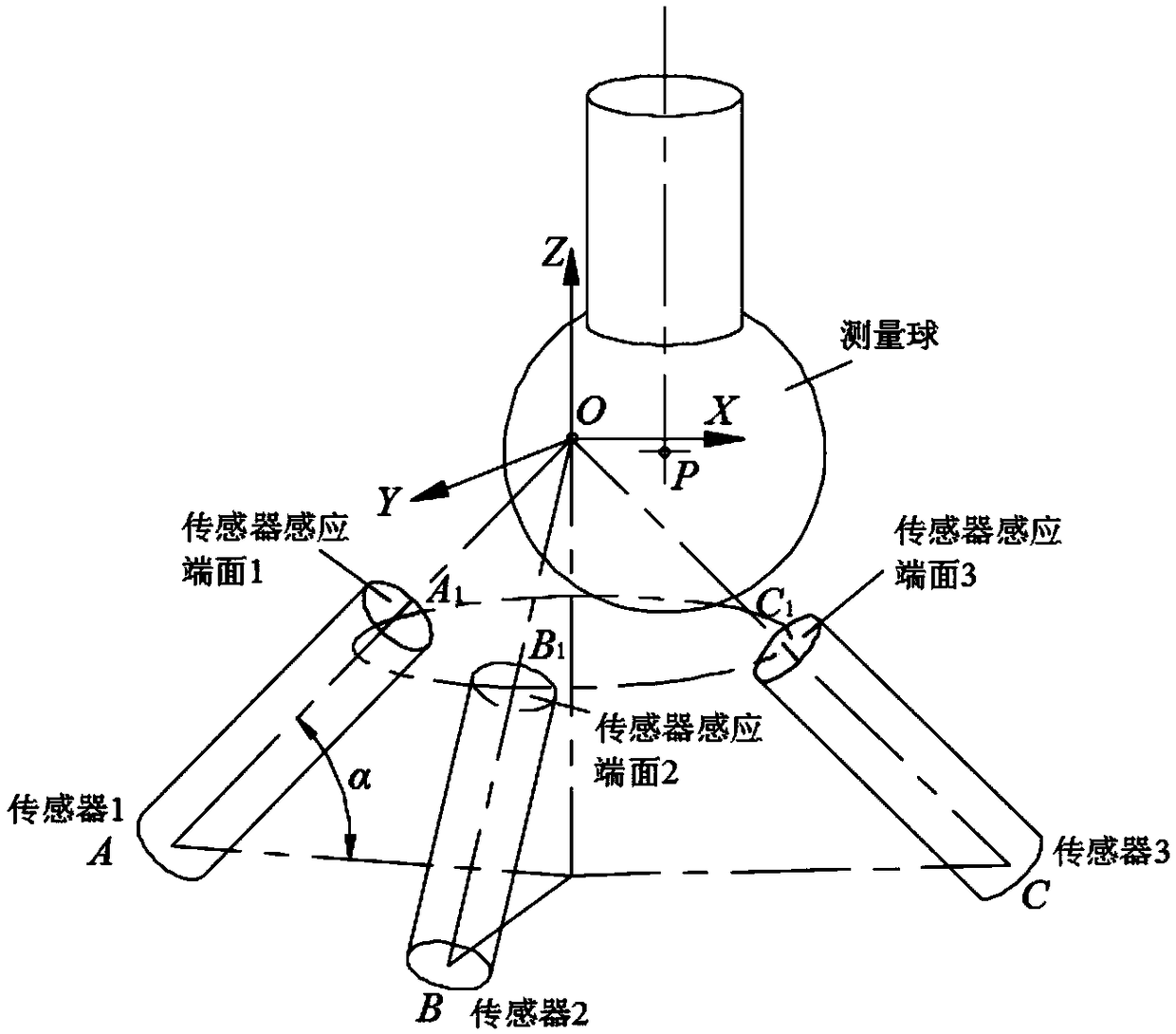
[0039] The structure model of the non-contact R-test measuring instrument using the eddy current displacement sensor is as follows figure 1 As shown, it mainly includes 3 evenly distributed eddy current displacement sensors and a standard measuring ball. According to the shortest distance spatial position relationship between the sensor plane and the measuring ball, the coordinate calculation of the center point P of the measuring ball is performed.

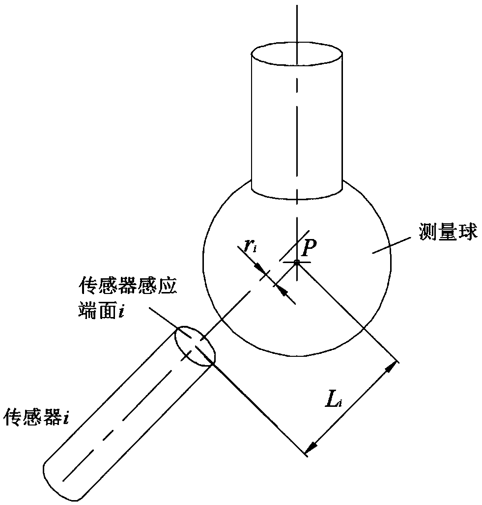
[0040] figure 1 Medium AA 1 , BB 1 , CC 1 Is 3 eddy current displacement sensor axes (A 1 , B 1 , C 1 It is the center point of the sensing plane of the 3 sensors, A, B, C are the center points of the bottom ends of the 3 sensors), the end of the sensor is the radius of R Explore The sensing plan...


PUM


Abstract

The invention discloses a calculating method for a ball center coordinate of a non-contact R-test measuring instrument using an eddy current displacement sensor. The calculating method includes the steps that a measuring coordinate system of the non-contact R-test measuring instrument is calibrated according to design and measuring characteristics of the non-contact R-test measuring instrument; and a coordinate result of a ball center point in the measuring coordinate system is solved and exacted using a differential evolution algorithm according to an eddy current displacement sensor inducedvoltage characteristic curve equation and a sensor induced plane equation. According to the calculating method for the ball center coordinate of the non-contact R-test measuring instrument using the eddy current displacement sensor, accurate measuring of three-direction displacement errors of five-axis numerically controlled machine tool knife tool cutter location points is realized, and the measuring accuracy, range and stability are better.

Description

Technical field [0001] The invention relates to the technical field of error measurement of numerical control machine tools, in particular to a method for calculating spherical center coordinates of a non-contact R-test measuring instrument using an eddy current displacement sensor. Background technique [0002] With the improvement of machining accuracy, the geometric error measurement of five-axis CNC machine tools has become increasingly important. For the rotation axis of five-axis CNC machine tools, accurate measurement of the error of the machine tool tip point is the key to error compensation to improve its machining accuracy. There are no special precision measuring instruments and specifications for the geometric error measurement of the machine tool rotation axis. The measuring instruments usually used are ballbar and laser interferometer. However, these measuring instruments are not dedicated to the error measurement of the rotating shaft, and have disadvantages such a...

Claims


Application Information

Patent Timeline
IPC IPC(8): G05B19/401
CPCG05B19/401G05B2219/34242
Inventor 丁国富江磊朱绍维彭炳康丁国华张剑邹益胜
Owner SOUTHWEST JIAOTONG UNIV
Why Eureka
Try Eureka