Differential microstrip filter antenna fed by balun filter

A balun filter, filter antenna technology, applied in resonant antennas, waveguide devices, antenna grounding devices, etc., to achieve the effect of reducing the structure volume, widening the working bandwidth, and obvious out-of-band suppression effect

Inactive Publication Date: 2018-12-18
HANGZHOU DIANZI UNIV
View PDF2 Cites 14 Cited by
  • Summary
  • Abstract
  • Description
  • Claims
  • Application Information

AI Technical Summary

Problems solved by technology

[0004] It can be seen from the above that there are few implementation methods of differentially fed filter antennas in the prior art, especially miniaturized and integrated differentially fed filter antennas

Method used


Image

  • Differential microstrip filter antenna fed by balun filter
  • Differential microstrip filter antenna fed by balun filter
  • Differential microstrip filter antenna fed by balun filter

Examples


Embodiment Construction

[0026] The present invention is further analyzed below in conjunction with specific examples.

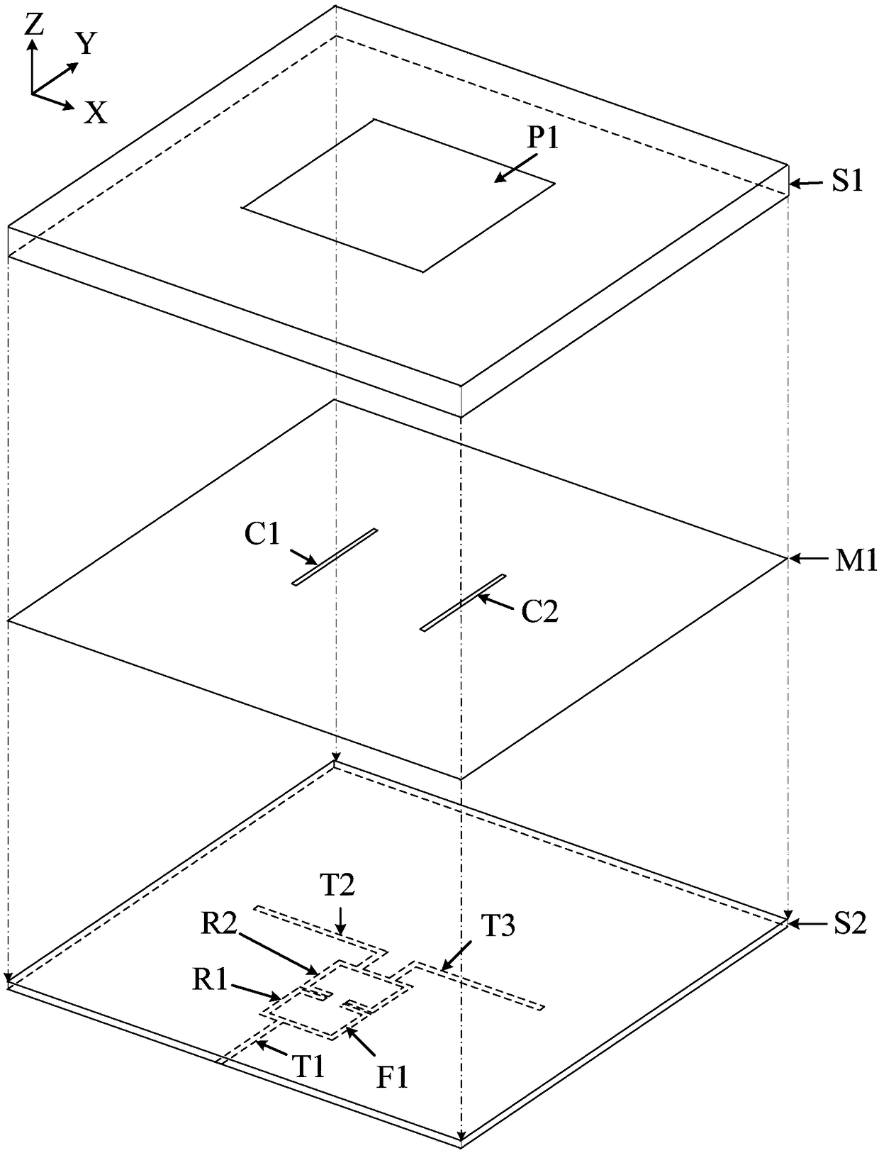
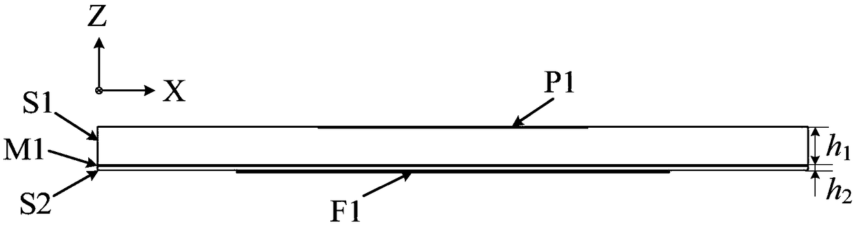
[0027] combine figure 1 and figure 2 , a differential microstrip filter antenna fed by a balun filter, including an upper dielectric substrate S1, a lower dielectric substrate S2, a square radiation patch P1, a ground plane M1, a feeding balun filter F1, and coupling slots C1 and C2.

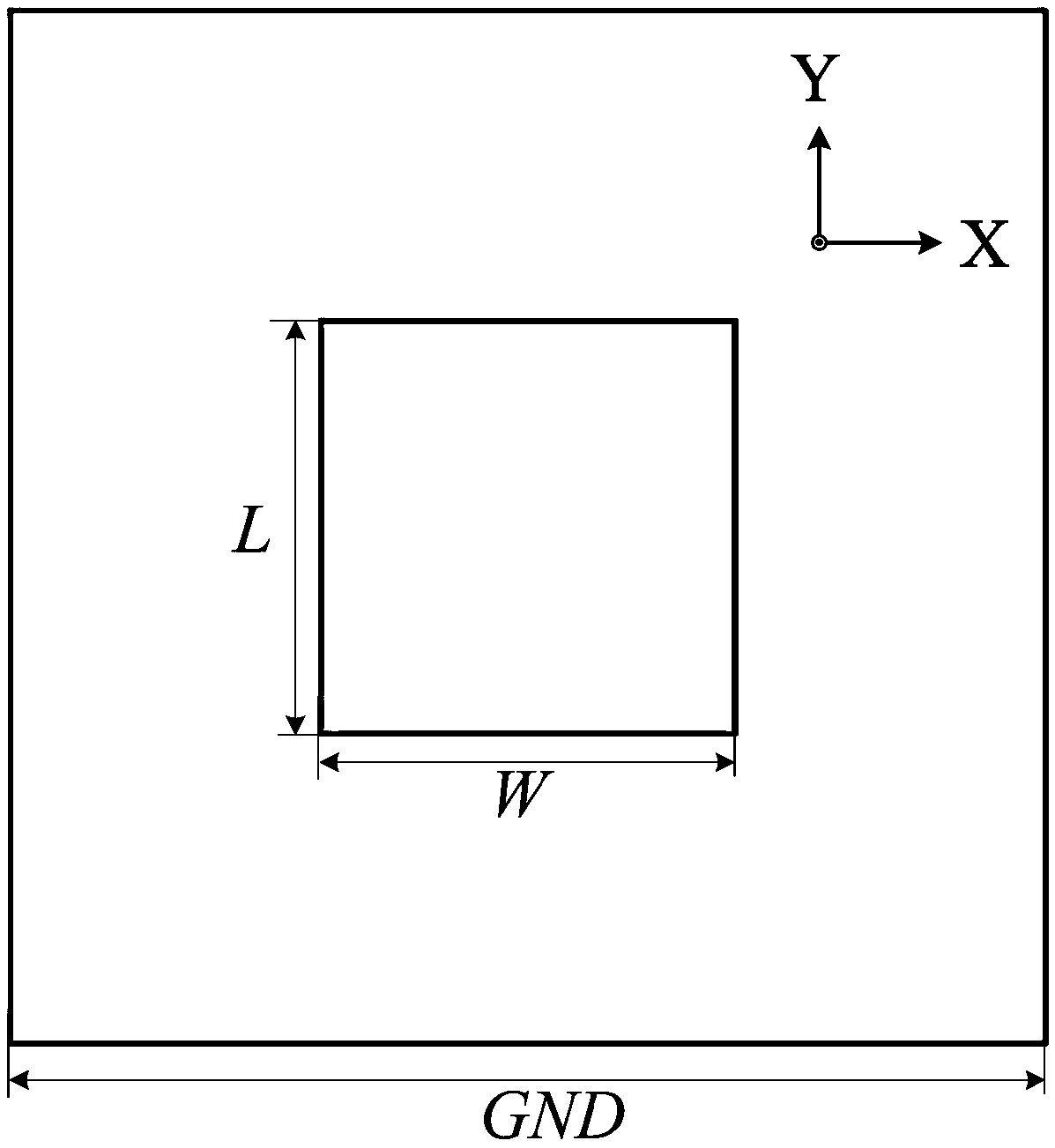
[0028] The dielectric substrate S1 is on the upper layer, and the dielectric substrate S2 is on the lower layer, and the two are separated by the ground plane M1. The square radiation patch P1 is located at the center of the upper surface of the dielectric substrate S1. Two type I coupling slots C1 and C2 are etched on the ground plane M1 and are symmetrical about the Y axis. The feed balun filter F1 is located on the lower surface of the dielectric substrate S2.

[0029] The balun filter F1 is composed of two mirror-symmetrical C-type half-wavelength resonators R1 and R2, an input microstrip lin...


PUM


Abstract

The invention relates to a differential microstrip filter antenna fed by a balun filter. The structure uses a balun filter to generate the differential signal with filtering characteristics, which excites the differential fed microstrip antenna, and realizes the miniaturized differential fed microstrip antenna with filtering and radiation characteristics at the same time. The filter antenna has stable gain in the pass band, fast gain drop out of the pass band and good edge selectivity. In addition, the radiation pattern of the structure is symmetrical and the cross polarization can achieve -35dB. on both the E plane and the H plane.

Description

technical field [0001] The invention relates to a differential microstrip filter antenna fed by a balun filter, which can be used as an antenna for a radio frequency front end of a miniaturized wireless transceiver and is widely used in wireless communication systems such as mobile communication, satellite communication and radar. Background technique [0002] With the development of wireless communication systems, the RF front-end structure is developing in the direction of multi-function, miniaturization and integration. Antennas and filters are two indispensable parts of the RF front-end. Traditional designs usually focus on the performance of a single device itself, and then use 50Ω transmission lines or impedance matching networks for cascading. Such a design scheme has a large structure size, and cascade connection is likely to cause impedance mismatch. In order to overcome these problems, the researchers proposed a filter antenna that can realize radiation and filter...

Claims


Application Information

Patent Timeline
Patent Type & Authority Applications(China)
IPC IPC(8): H01Q1/38H01Q1/48H01Q9/04H01P1/20
CPCH01P1/20H01Q1/38H01Q1/48H01Q9/04
Inventor 金华燕罗国清张晓红袁博范奎奎
Owner HANGZHOU DIANZI UNIV
Why Eureka
Try Eureka