
Low voltage power take-off system

An electric system and low-voltage technology, which is applied in the field of low-voltage power-taking systems, can solve the problems of large space occupation and long installation time

Pending Publication Date: 2018-12-18
GUANGZHOU POWER SUPPLY BUREAU GUANGDONG POWER GRID CO LTD
View PDF0 Cites 0 Cited by
  • Summary
  • Abstract
  • Description
  • Claims
  • Application Information

AI Technical Summary

Problems solved by technology

[0004] Based on this, it is necessary to provide a low-voltage power-taking system for the problems of long installation time and large space occupation in the low-voltage power-taking system of the data transmission unit

Method used


Image

  • Low voltage power take-off system

Examples


Embodiment Construction

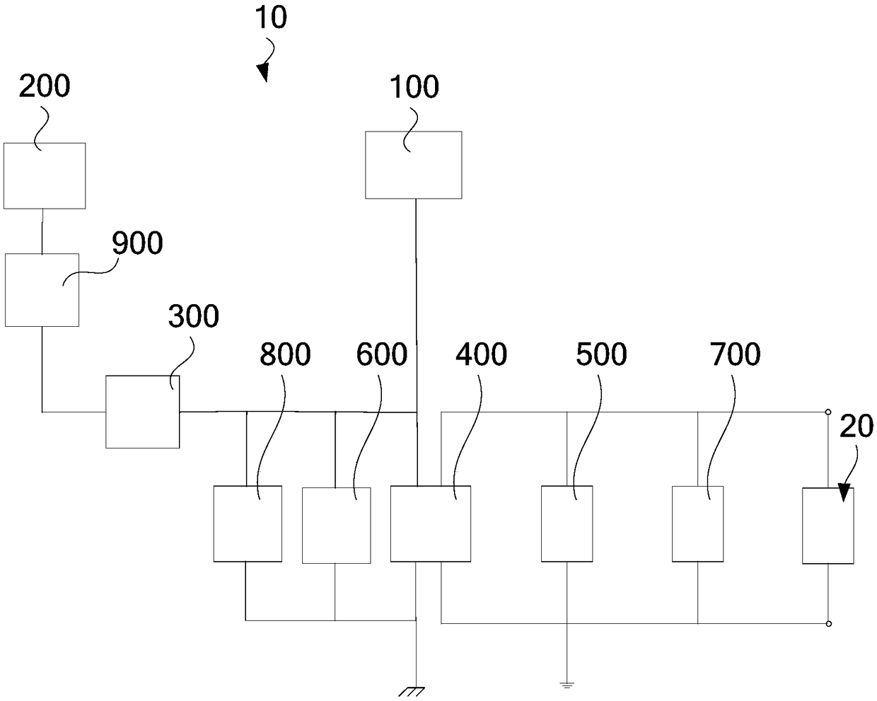
[0020] In order to facilitate the understanding of the present invention, a more comprehensive description of the low-voltage power-taking system will be given below with reference to the relevant drawings. The preferred embodiment of the low-voltage power-taking system is given in the accompanying drawings. However, the low-voltage power extraction system can be implemented in many different forms, and is not limited to the embodiments described herein. On the contrary, the purpose of providing these embodiments is to make the disclosure of the low-voltage power-taking system more thorough and comprehensive.

[0021] It should be noted that when an element is referred to as being “fixed” to another element, it can be directly on the other element or there can also be an intervening element. When an element is referred to as being "connected to" another element, it can be directly connected to the other element or intervening elements may also be present. The terms "vertical...


PUM


Abstract

The invention relates to a low-voltage power take-off system. The low-voltage power take-off system comprises a solar energy power take-off device, a current transformer power take-off device, an AC / DC conversion circuit module, a ternary battery charging controller and a ternary battery module. A solar energy power take-off device is used for converting solar energy into electric energy; The current transformer power take-off device is used for electrically connecting with the incoming cable of the distribution network switch room; The AC / DC conversion circuit module is arranged in series with the current transformer power fetching device; The ternary battery charging controller is electrically connected with the solar energy power fetching device and the AC / DC conversion circuit module respectively. The ternary battery module and the ternary battery charging controller are arranged in parallel. When both the current transformer and solar energy devices lose power, the three-element battery module automatically supplies power to the equipment load and can last for 6- 7 hours to meet the daily power demand of the equipment load.

Description

technical field [0001] The invention relates to the technical field of power distribution, in particular to a low-voltage power taking system. Background technique [0002] The data transmission unit is used for converting serial port data into IP data or converting IP data into serial port data and transmitting the wireless terminal equipment through the wireless communication network. The data transmission unit is widely used in power distribution, meteorology, hydrology and water conservancy, geology and other industries. [0003] The low-voltage power-taking system of the data transmission unit of the traditional power distribution room usually adopts the method of splicing voltage transformer cabinets or small substation transformers. The above-mentioned low-voltage power-taking system of the data transmission unit has the problems of long installation time and large space occupation. Contents of the invention [0004] Based on this, it is necessary to provide a low...

Claims


Application Information

Patent Timeline
Patent Type & Authority Applications(China)
IPC IPC(8): H02J7/35H02S20/23H02J5/00H02J50/10H02J7/00H02H9/04
CPCH02J5/005H02J7/025H02H9/04H02J7/00H02J7/35H02J50/10H02S20/23Y02E10/50Y02B10/10
Inventor 邹嘉焜张锋何悦吴日昇邓国豪刘剑毕炳昌张尧简峻叶常禄
Owner GUANGZHOU POWER SUPPLY BUREAU GUANGDONG POWER GRID CO LTD
Learn More