A voltage doubling type three-winding coupled inductance high-gain DC converter

A technology of DC converter and coupled inductor, which is applied in the direction of converting DC power input to DC power output, adjusting electrical variables, instruments, etc. It can solve the problems of limited boosting capacity and inapplicability to high-gain DC power conversion occasions, and achieve high Effect of Voltage Gain

Active Publication Date: 2018-12-18
HARBIN INST OF TECH
View PDF5 Cites 6 Cited by
  • Summary
  • Abstract
  • Description
  • Claims
  • Application Information

AI Technical Summary

Problems solved by technology

[0003] The purpose of the present invention is to solve the problem that the current boost converter is used to achieve voltage gain, but the actual gain of the boost converter does not always increase with the increase of the duty cycle, and its boost capacity is very limited, so it is not suitable for high Problems in Gain-to-DC Power Conversion Applications

Method used


Image

  • A voltage doubling type three-winding coupled inductance high-gain DC converter
  • A voltage doubling type three-winding coupled inductance high-gain DC converter
  • A voltage doubling type three-winding coupled inductance high-gain DC converter

Examples


specific Embodiment approach 1

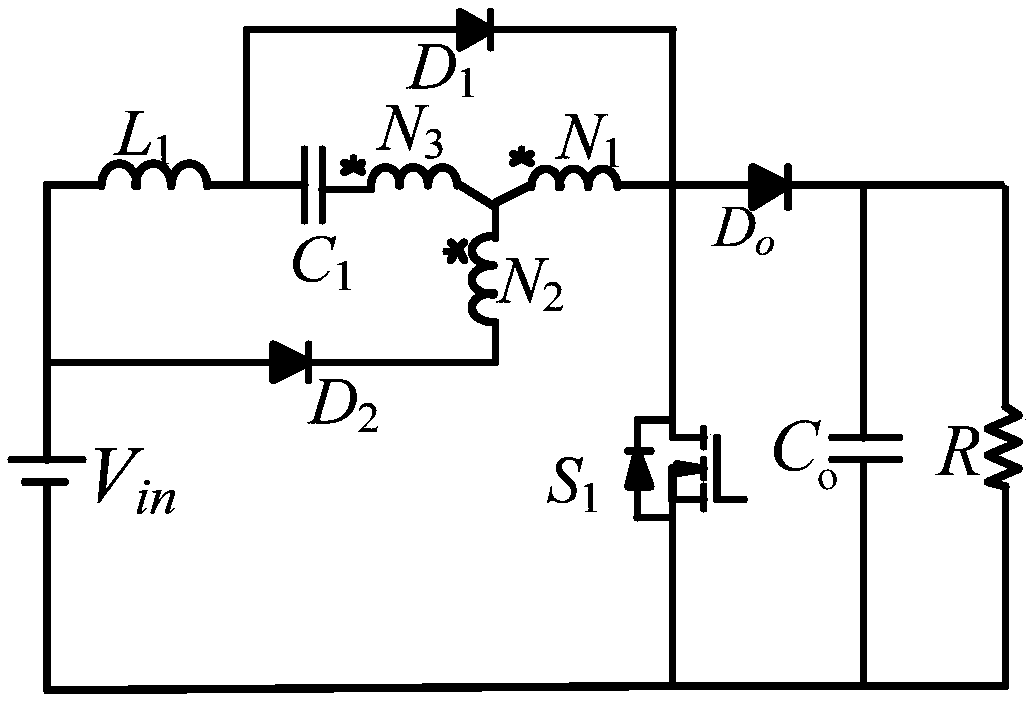
[0018] Specific Embodiment 1: A voltage doubler type three-winding coupled inductor high-gain DC converter described in this embodiment includes a three-winding coupled inductor winding, a voltage doubler structure, and a power switch tube S 1 and output diode D o ,

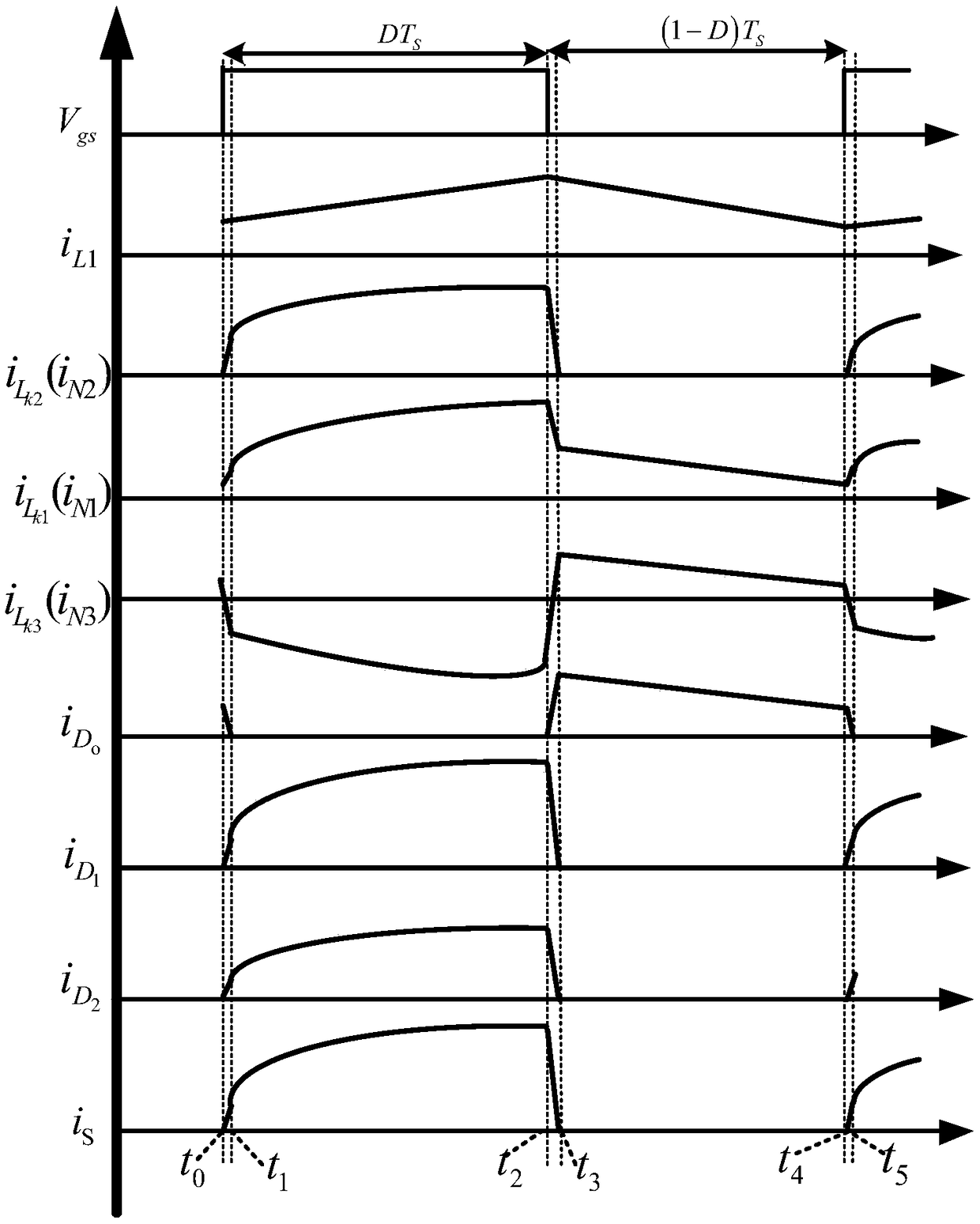
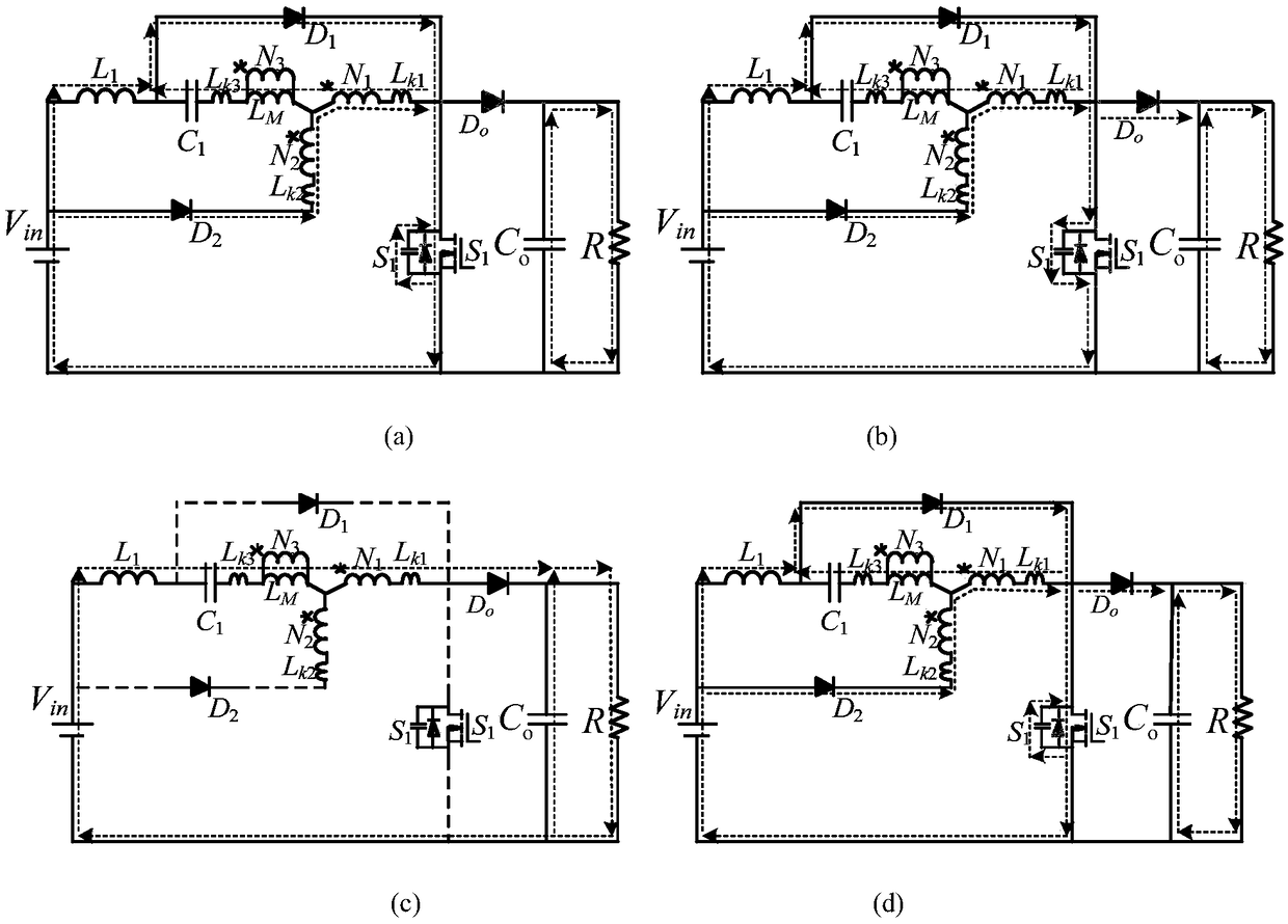
[0019] The three-winding coupled inductor winding is used in the power switch tube S 1 When turned on, the DC voltage source V in The input energy is stored and amplified through the doubler structure;

[0020] Also used in the power switch tube S 1 When it is turned off, use the power switch tube S 1 The parasitic capacitance absorbs the leakage inductance energy, so that the power switch S 1 The voltage across both ends is higher than the output capacitor C o The voltage across both ends turns on the output diode D o , will amplify the energy through the output diode D o for the load R and the output capacitor C o powered by.

specific Embodiment approach 2

[0021] Specific implementation mode two: refer to figure 1 Describe this embodiment in detail. This embodiment is a further description of a voltage-doubler type three-winding coupled inductor high-gain DC converter described in Embodiment 1. In this embodiment, it also includes an inductor L 1 ,

[0022] DC voltage source V in Give the inductor L through the voltage doubler structure 1 charging, the power switch S 1 When turned off, the inductance L 1 for the load R and the output capacitor C o powered by.

specific Embodiment approach 3

[0023] Specific implementation mode three: refer to figure 1 This embodiment is described in detail. This embodiment is a further description of a voltage doubler type three-winding coupled inductor high-gain DC converter described in the first or second specific embodiment. In this embodiment, the three-winding coupled inductor winding includes coupling Inductor winding N 1 , coupled inductor winding N 2 and coupled inductor winding N 3 ,

[0024] The voltage doubler structure consists of a diode D 1 , Diode D 2 and capacitance C 1 ,

[0025] DC voltage source V in The positive pole is connected to the inductor L at the same time 1 one end of the diode D 2 positive pole, the inductor L 1 The other end of the capacitor C is connected at the same time 1 one end of the diode D 1 the anode of the diode D 1 The negative pole of the power switch tube S is connected 1 The drain of the power switch S 1 The source is connected to the DC voltage source V at the same time...


PUM


Abstract

The invention relates to a voltage doubling type three-winding coupled inductance high-gain DC converter, which relates to the technical field of power electronic converters. The present invention aims to solve the problem that the voltage gain is realized by using a boost converter, but the actual gain of the boost converter does not always increase with the increase of the duty cycle, and the boost capacity is very limited, so that the present invention is not suitable for the situation of high-gain DC power conversion. A three-winding coupled inductor winding for storing energy input from aDC voltage source Vin when the power switch S1 is turned on and amplifying the energy by a voltage doubling structure; It is also used for absorbing leakage inductance energy by parasitic capacitanceof the power switch S1 when the power switch S1 is turned off, so that the voltage at both ends of the power switch S1 is higher than the voltage at both ends of the output capacitance Co, the outputdiode Do is turned on, and the amplified energy is supplied to the load R and the output capacitance Co through the output diode Do. It is used to obtain high gain voltages.

Description

technical field [0001] The invention relates to a three-level high-gain DC converter, which belongs to the technical field of power electronic converters. Background technique [0002] The boost converter is widely used in the front-end converter of the distributed power system to realize boost or power factor correction. The traditional boost converter circuit topology is a Boost circuit. In theory, the voltage gain of the Boost circuit increases with the increase of the duty cycle. However, considering the parasitic equivalent series impedance in the actual circuit, the actual gain of the Boost circuit is not always It becomes larger as the duty cycle increases, so its boost capability is very limited, and it is not suitable for high-gain DC power conversion applications. Contents of the invention [0003] The purpose of the present invention is to solve the problem that the current boost converter is used to achieve voltage gain, but the actual gain of the boost conver...

Claims


Application Information

Patent Timeline
Patent Type & Authority Applications(China)
IPC IPC(8): H02M3/156
CPCH02M3/156H02M1/0064
Inventor 刘洪臣纪玉亮
Owner HARBIN INST OF TECH
Why Eureka
Try Eureka