
Time-frequency standard signal fusion transmission system and transmission method

A standard signal and transmission system technology, which is applied in the field of time-frequency standard signal transmission, and can solve the problems of inability to transmit time reference signals at the same time, high cost, and no spectral purification at the remote end.

Active Publication Date: 2018-12-18
SHANGHAI INST OF OPTICS & FINE MECHANICS CHINESE ACAD OF SCI
View PDF3 Cites 25 Cited by
  • Summary
  • Abstract
  • Description
  • Claims
  • Application Information

AI Technical Summary

Problems solved by technology

However, the use of optical combs for time-frequency standard signal transmission has the following problems: 1) Mode-locked lasers need to be used, and the cost is high; 2) The delay of the optical fiber needs to be adjusted so that the local pulse chain and the return pulse chain are properly overlapped; Dispersion is strictly controlled; 4) The remote end does not perform spectral purification; 5) It is impossible to transmit 1pps time reference signal at the same time
[0007] As mentioned above, both the existing transmission scheme based on intensity modulation and direct detection and the transmission scheme based on femtosecond optical frequency comb have some defects, so that the time-frequency standard signals in the radio frequency domain and the optical frequency domain cannot be simultaneously fused and transmitted to the remote user

Method used


Image

  • Time-frequency standard signal fusion transmission system and transmission method
  • Time-frequency standard signal fusion transmission system and transmission method
  • Time-frequency standard signal fusion transmission system and transmission method

Examples


Embodiment Construction

[0097] The present invention will be further described below in conjunction with the embodiments and accompanying drawings, but the protection scope of the present invention should not be limited thereby.

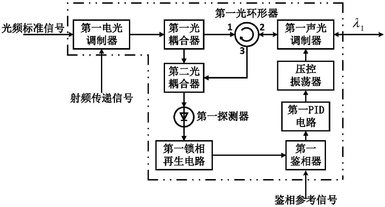
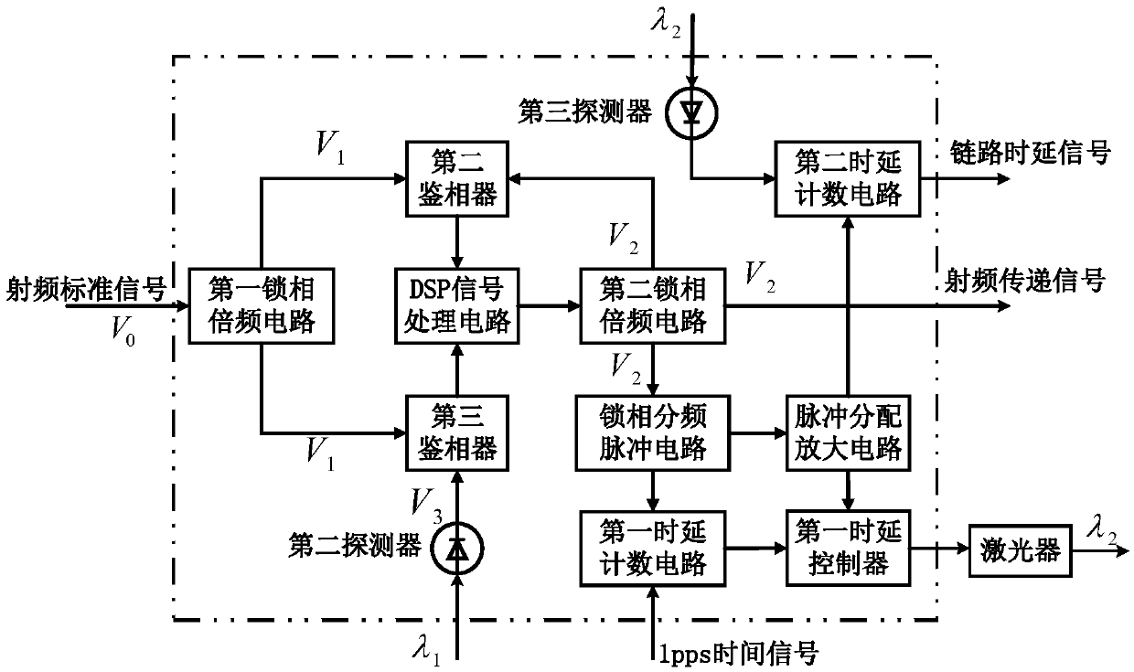
[0098] see figure 1 , figure 1It is a structural schematic diagram of the time-frequency standard signal fusion transmission system of the present invention. It can be seen from the figure that the time-frequency standard signal fusion transmission system of the present invention includes: compensation module 1, which is used to modulate the radio frequency transmission signal onto the optical frequency standard signal, and compensate The phase noise introduced when the optical frequency standard signal is transmitted in the optical fiber link; the compensation module 2 is used to calculate the delay of the link, generate the radio frequency transmission signal, and compensate the RF standard signal and time signal introduced during the transmission of the optical fiber lin...


PUM


Abstract

A time-frequency standard signal fusion transmission system and transmission method are provided. The system compensates the phase noise of optical frequency signal, radio frequency signal and time signal when they are transmitted in the optical fiber link through the compensation module 1, the compensation module 2 and the communication signal transmitter of the local terminal, and sends the calculated link delay to the remote terminal together with the communication data. Through the optical frequency and RF reference signal output module at the remote end, The time signal output module andthe communication signal receiver, the spectrum purification of the optical frequency standard signal, the spectrum purification of the radio frequency standard signal and the time delay calibration of the time signal are realized, so that the user can simultaneously obtain the high-quality optical frequency standard signal, the radio frequency standard signal, the time signal and the communication data signal. The technical scheme of the invention solves the problems of mutual crosstalk and low detection signal-to-noise ratio when a plurality of signals are simultaneously transmitted, and greatly improves the transmission distance and transmission accuracy of the transmission of the plurality of standard signals.

Description

technical field [0001] The invention relates to the technical field of time-frequency standard signal transmission, in particular to a fusion transmission system and method of an optical frequency standard, a radio frequency standard, a time signal and a data signal. Background technique [0002] High-precision and accurate time-frequency standards are common basic issues and core key technologies in major infrastructure construction and cutting-edge scientific research such as precise punctuality and timing, precise navigation and positioning, radar networking, deep space exploration, and mobile communications. . [0003] These time-frequency standards include rubidium or cesium atomic fountain clocks in the radio frequency domain. After continuous development in recent years, the uncertainty of their frequency has reached 10 -16 order of magnitude. In the field of optical frequency, the frequency stability and uncertainty of optical atomic clocks such as lattice clocks a...

Claims


Application Information

Patent Timeline
IPC IPC(8): H04B10/516H04B10/25
CPCH04B10/25H04B10/516
Inventor 冯子桐杨飞张茜吴瑞孙延光程楠蔡海文桂有珍
Owner SHANGHAI INST OF OPTICS & FINE MECHANICS CHINESE ACAD OF SCI
Learn More