A cooling device for electronic products that improves the cooling efficiency of cooling water

A technology for cooling efficiency and electronic products, which is applied in the construction of electrical equipment components, cooling/ventilation/heating transformation, electrical components, etc., can solve the problem that the residence time of the cooling liquid in the cooling tank cannot be adjusted flexibly, and the temperature of the cooling liquid cannot be adjusted reasonably Control and affect the cooling effect of electronic equipment and other issues to achieve the effect of ensuring the cooling effect and improving the utilization rate

Active Publication Date: 2020-07-03
安徽好润环保科技有限公司
View PDF8 Cites 0 Cited by
  • Summary
  • Abstract
  • Description
  • Claims
  • Application Information

AI Technical Summary

Problems solved by technology

[0003] During the production and processing of electronic equipment, it is necessary to cool down the electronic equipment. The existing devices basically use coolant to cool down the electronic equipment. For some cooling liquid circulation devices, the residence time of the cooling liquid in the cooling tank cannot be adjusted flexibly, because the temperature of the electronic equipment placed in the cooling tank is different, but the temperature of the cooling liquid in the cooling tank cannot be reasonably controlled, thus greatly Affect the cooling effect of electronic equipment

Method used


Image

  • A cooling device for electronic products that improves the cooling efficiency of cooling water
  • A cooling device for electronic products that improves the cooling efficiency of cooling water
  • A cooling device for electronic products that improves the cooling efficiency of cooling water

Examples


Embodiment 1

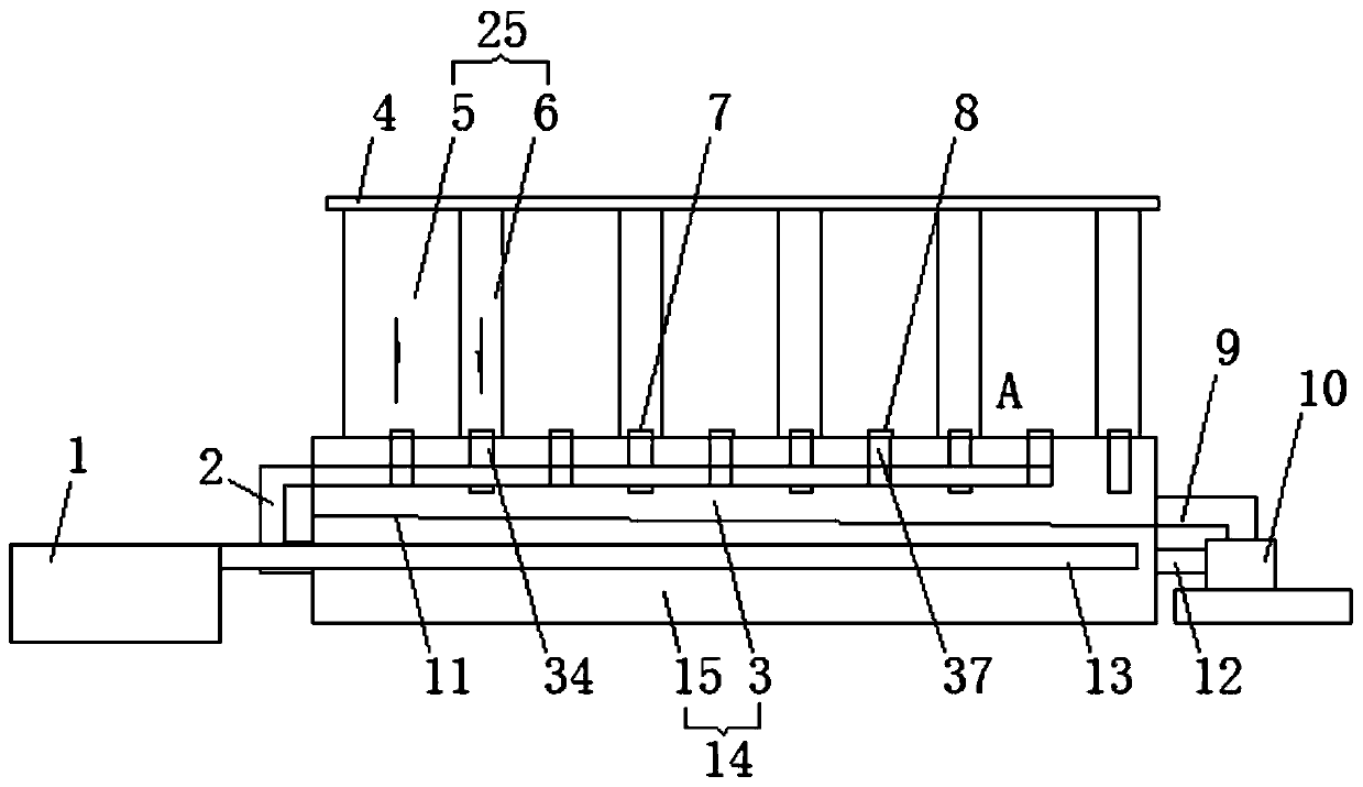
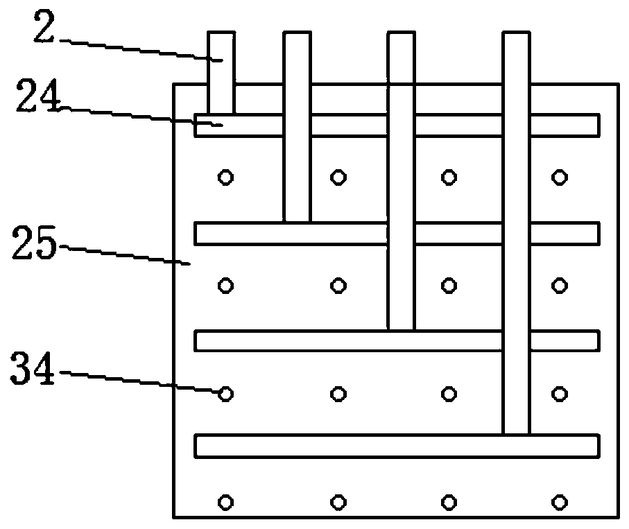
[0035] Example 1, see Figure 1-7 , a flow regulating device for electronic product cooling equipment, including a base 14 and a cooling box 25, the cooling box 25 is provided with a number of parallel and staggered cooling grooves 5 and circulation grooves 6, the cooling grooves 5 and A number of uniformly distributed cooling sub-grooves 18 and circulation sub-grooves 19 are respectively arranged in the circulation tank 6, and the bottoms of the cooling sub-grooves 18 and the circulation sub-grooves 19 are respectively provided with a liquid inlet 8 and a liquid outlet 7. The liquid inlet 8 and the bottom of the liquid outlet 7 are provided with a liquid inlet pipe 37 and a liquid outlet pipe 34, and the bottoms of the liquid inlet pipe 37 are connected by first connecting pipes 24 parallel to each other. There is a connected second connecting pipe 2, the bottom of the cooling box 25 is provided with a base 14, and the base 14 is respectively provided with a collection tank 3...

Embodiment 2

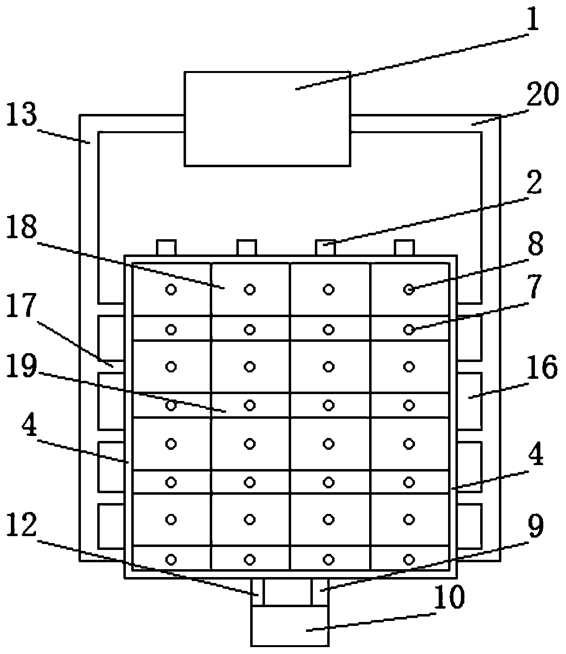
[0036] Example 2, see Figure 8 , a flow regulating device for electronic product cooling equipment, including a base 14 and a cooling box 25, the cooling box 25 is provided with a number of parallel and staggered cooling grooves 5 and circulation grooves 6, the cooling grooves 5 and In the circulation tank 6, several evenly distributed cooling sub-grooves 18 and circulation sub-grooves 19 are respectively provided. The liquid inlet 8 and the bottom of the liquid outlet 7 are provided with a liquid inlet pipe 37 and a liquid outlet pipe 34, and the bottoms of the liquid inlet pipe 37 are connected by first connecting pipes 24 parallel to each other. There is a connected second connecting pipe 2, the bottom of the cooling box 25 is provided with a base 14, and the base 14 is respectively provided with a collection tank 3 and a water cooling tank 15 from top to bottom, and the collection tank 3 is located at the exit Directly below the liquid pipe 34, and one side of the collecti...

Embodiment 3

[0037] Example 3, see Figure 9 , a flow regulating device for electronic product cooling equipment, including a base 14 and a cooling box 25, the cooling box 25 is provided with a number of parallel and staggered cooling grooves 5 and circulation grooves 6, the cooling grooves 5 and In the circulation tank 6, several evenly distributed cooling sub-grooves 18 and circulation sub-grooves 19 are respectively provided. The liquid inlet 8 and the bottom of the liquid outlet 7 are provided with a liquid inlet pipe 37 and a liquid outlet pipe 34, and the bottoms of the liquid inlet pipe 37 are connected by first connecting pipes 24 parallel to each other. There is a connected second connecting pipe 2, the bottom of the cooling box 25 is provided with a base 14, and the base 14 is respectively provided with a collection tank 3 and a water cooling tank 15 from top to bottom, and the collection tank 3 is located at the exit Directly below the liquid pipe 34, and one side of the collec...


PUM


Abstract

The invention discloses a flow regulating device for electronic product cooling equipment, the device comprises a base and a cooling box, the cooling box is provided with a plurality of parallel and staggered cooling grooves and circulating grooves, the cooling groove and the circulating groove are respectively provided with a plurality of evenly distributed cooling sub-grooves and circulating sub-grooves, A base is arranged at the bottom of the cooling box, A collection tank and a water cooling tank are respectively arranged in the base from the top to the bottom, the collecting tank and thewater cooling tank are connected with each other by a first water pump, A liquid inlet pipe and a liquid outlet pipe are connected with the cooling water circulation tank on both sides of the water cooling tank through an inlet pipe and an outlet pipe, and valve are arranged on the liquid inlet pipe and the liquid outlet pipe, A handle is arrange on the valve, the bottom of the handle is connectedthrough a plurality of parallel distribute adjusting rods, one side of the adjusting rod is provided with an adjusting block, and a rack is arrange on the adjusting rod, an adjusting shaft meshing with the rack is arranged in the adjusting block, and an adjusting rotary table is arranged on the outer side of the adjusting shaft, which has strong comprehensive practicability and is easy to popularize and use.

Description

Technical field: [0001] The invention relates to an electronic product cooling device, in particular to a flow regulating device for the electronic product cooling device. Background technique: [0002] Electronic equipment refers to equipment composed of integrated circuits, transistors, electronic tubes and other electronic components, which use electronic technology (including) software to play a role, including electronic computers, robots controlled by electronic computers, numerical control or program-controlled systems, etc. [0003] During the production and processing of electronic equipment, it is necessary to cool down the electronic equipment. The existing devices basically use coolant to cool down the electronic equipment. For some cooling liquid circulation devices, the residence time of the cooling liquid in the cooling tank cannot be adjusted flexibly, because the temperature of the electronic equipment placed in the cooling tank is different, but the tempera...

Claims


Application Information

Patent Timeline
Patent Type & Authority Patents(China)
IPC IPC(8): H05K7/20
CPCH05K7/20272
Inventor 周龙周建明乔峰乔柱
Owner 安徽好润环保科技有限公司
Why Eureka
Try Eureka