Vertical high-speed small horizontal screw centrifuge

A decanter centrifuge, high-speed technology, applied to centrifuges, centrifuges with rotating drums, etc., can solve problems such as low work efficiency, noise pollution, and insufficient safety, and achieve high work efficiency, reduce noise pollution, The effect of novel structure

Pending Publication Date: 2018-12-21
ZHANGJIAGANG LANNIAO MACHINERY CO LTD
View PDF13 Cites 1 Cited by
  • Summary
  • Abstract
  • Description
  • Claims
  • Application Information

AI Technical Summary

Problems solved by technology

[0003] In view of the above situation, in order to overcome the defects of the prior art, the present invention provides a vertical high-speed small decanter centrifuge, which solves the problem of low working efficiency, insufficient safety and noise pollution of the existing decanter centrifuge. question

Method used


Image

  • Vertical high-speed small horizontal screw centrifuge
  • Vertical high-speed small horizontal screw centrifuge
  • Vertical high-speed small horizontal screw centrifuge

Examples


Embodiment 1

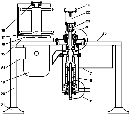
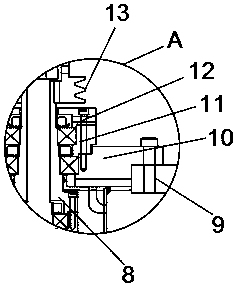
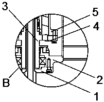
[0019] Embodiment one, by figure 1 , figure 2 with image 3 Given, the present invention includes a support platform 25, one side of the support platform 25 is provided with a motor 19, the motor 19 is controlled by an external switch, and the motor 19 and the support platform 25 are connected through a motor adjustment seat 15, which is convenient for adjusting the motor 19 Simple and convenient, the top of motor 19 is provided with belt support frame 16, and belt support frame 16 is provided with motor belt 17, and one end of motor 19 is provided with pulley, is connected by pulley bearing between pulley and motor 19, and pulley bearing and belt support frame The junction of 16 is provided with belt pulley bearing cover 18, rotates by motor 19 during use, drives belt pulley bearing and my pulley to rotate, then drives spiral belt pulley 14 and bowl belt pulley 13 by motor belt 17, promptly can have fast driving screw 6 and The rotating drum 5 is simple and convenient, and...

Embodiment 2

[0021] Embodiment two, on the basis of embodiment one, by figure 1 Provided, the bottom end of the support platform 25 is provided with a support foot 20, the bottom end of the support foot 20 is provided with a shock absorber 21, and the bottom end of the shock absorber 21 is provided with anti-slip lines, the depth of the anti-slip lines is ten centimeters, and the anti-slip lines Arranged in a circular shape, the support feet 20, shock absorbing pads 21 and anti-skid lines are used to make the whole more stable.

Embodiment 3

[0022] Embodiment three, on the basis of embodiment one, by Figure 5 Provided, the motor 19 and the supporting foot 20 are connected through a support plate 24, and the inside of the support plate 24 is provided with a shock absorbing chamber 2401, and the inside of the shock absorbing chamber 2401 is provided with a shock absorbing spring 2402, and one side of the shock absorbing spring 2402 is provided There are reinforcing ribs 2403, which can make the motor 19 more stable through the support plate 24 during use. noise pollution.


PUM


Abstract

The invention discloses a vertical high-speed small horizontal screw centrifuge. The problems that an existing horizontal screw centrifuge is low in working efficiency, is not safe enough and can generate noise pollution during working are solved. The centrifuge comprises a supporting table, a motor is arranged on one side of the supporting table, and the motor is connected with the supporting table through a motor adjusting base; a belt supporting frame is arranged at the top end of the motor, a motor belt is arranged on the belt supporting frame, a belt pulley is arranged at one end of the motor, and the belt pulley is connected with the motor through a belt pulley bearing; a belt pulley bearing cover is arranged at the joint of the belt pulley bearing and the belt supporting frame, a spiral is arranged in the middle, located in one side of the motor, of the supporting table, and a spiral belt pulley is arranged at the top end of the spiral. According to the centrifuge, the structureis novel, the spiral and a rotating drum can be quickly driven, simple and convenient are achieved, and working efficiency is high; and meanwhile, a first rotating drum end shaft and a second rotating drum end shaft can be effectively protected, simpleness and safety are achieved, and noise pollution when the motor works can be reduced.

Description

technical field [0001] The invention relates to the technical field of decanter centrifuges, in particular to a vertical high-speed small decanter centrifuge. Background technique [0002] The decanter centrifuge is a horizontal spiral unloading, continuous operation settling equipment. This machine can continuously feed, separate, wash and unload at full speed. It has the characteristics of compact structure, continuous operation, stable operation, strong adaptability, large production capacity and convenient maintenance. It is suitable for separating suspensions containing solid phases with a particle size greater than 0.005mm and a concentration range of 2-40%. Widely used in industries such as chemical industry, light industry, pharmacy, food, environmental protection, and existing decanter centrifuge, and existing decanter centrifuge work efficiency is low, not safe enough, and can produce noise pollution when working. Contents of the invention [0003] In view of t...

Claims


Application Information

Patent Timeline
Patent Type & Authority Applications(China)
IPC IPC(8): B04B1/20B04B9/08B04B15/00
CPCB04B1/20B04B1/2016B04B15/00
Inventor 黄韧浩
Owner ZHANGJIAGANG LANNIAO MACHINERY CO LTD
Why Eureka
Try Eureka