

Sheet laser scanning filler wire welding method
A technology of laser scanning and welding methods, which is applied in laser welding equipment, welding equipment, metal processing equipment, etc., can solve problems such as welding deformation, uneven weld seam, poor quality and mechanical properties of weld seam joints, and promote metallurgical bonding , increase the reflection effect, improve the effect of welding efficiency
- Summary
- Abstract
- Description
- Claims
- Application Information
AI Technical Summary
Problems solved by technology
Method used
Image

Examples
Embodiment 1
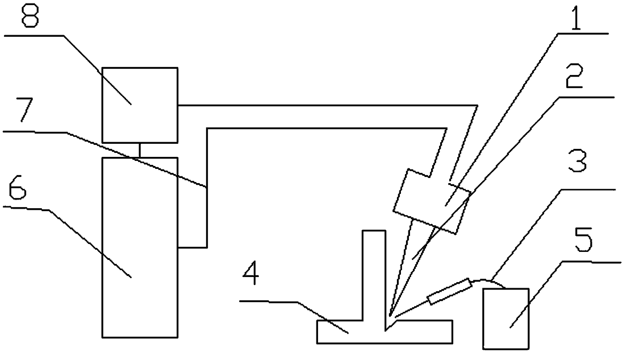
[0030] A thin plate laser scanning wire filling welding method, such as figure 1 As shown, the thin plate used in this embodiment is a T-shaped thin plate. By adopting the method of opening a half-V-shaped groove on the bottom plate of the right-angled structure of the T-shaped thin plate, combined with the laser scanning wire filling welding method, the right-angled structure of the T-shaped thin plate is effectively controlled. Weld seam quality, reduce welding deformation, enhance the metallurgical bonding between welding wire and base material, improve welding efficiency, and form high-quality T-shaped welded joints. The steps are:
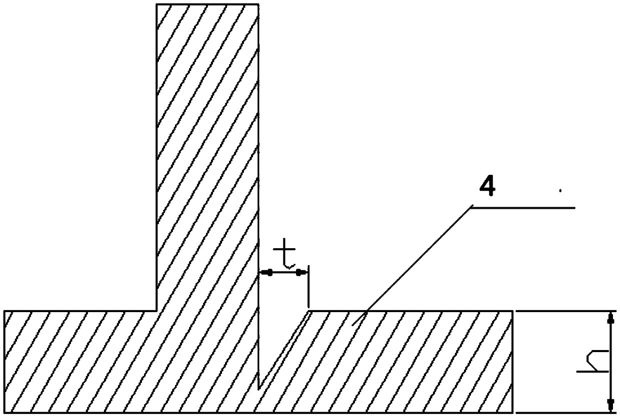
[0031] Step S1: The welded thin plate h is an spcc cold-rolled thin plate with a thickness of 1.5mm. At the T-shaped joint of the two thin plates to be welded, a half-V-shaped groove is opened on the bottom plate of the right-angle structure, such as figure 2 As shown, the groove width t is 0.8mm, and the processed groove and the surfaces on ...
Embodiment 2
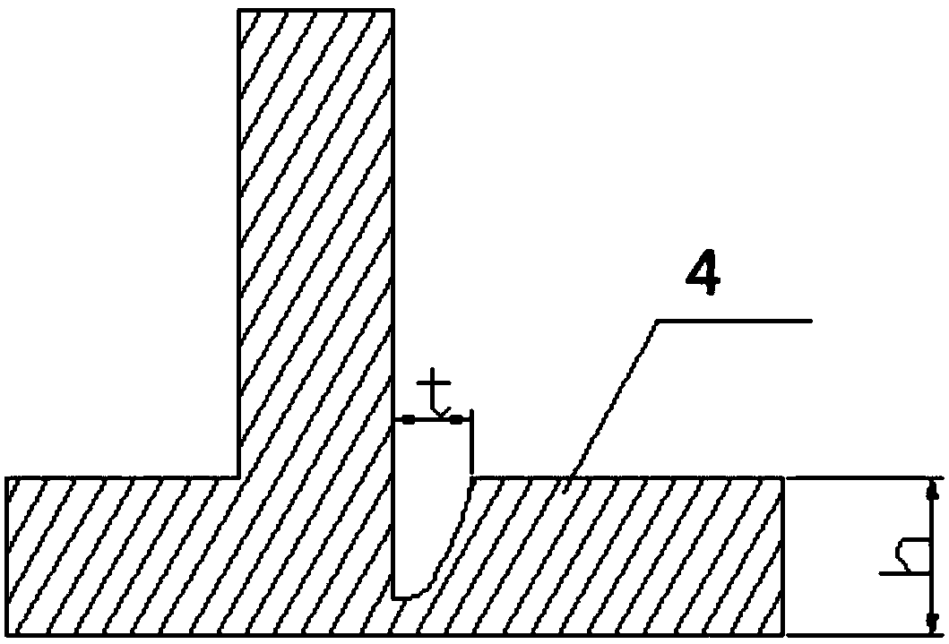
[0037] A thin plate laser scanning wire filling welding method, the thin plate used in this embodiment is a T-shaped thin plate, by adopting the method of opening a half U-shaped groove on the bottom plate of the right-angle structure of the T-shaped thin plate, such as image 3 As shown, combined with the laser scanning wire filling welding method, the weld seam quality of the T-shaped thin plate right-angle structure can be effectively controlled, the welding deformation can be reduced, the metallurgical bonding between the welding wire and the base material can be enhanced, the welding efficiency can be improved, and a high-quality T-shaped welded joint can be formed. The steps are:
[0038] Step S1: The welded thin plate h is an spcc cold-rolled thin plate with a thickness of 1.5 mm. At the T-shaped joint of the two thin plates to be welded, a semi-U-shaped groove is opened on the bottom plate of the right-angle structure, and the groove width t is 1.0 mm. Grinding and cle...
Embodiment 3
[0044] A thin plate laser scanning wire filling welding method, the thin plate used in this embodiment is a T-shaped thin plate, by adopting the method of opening a half V-shaped groove at the bottom plate of the right-angle structure of the T-shaped thin plate, such as figure 2 As shown, combined with the laser scanning wire filling welding method, the weld seam quality of the T-shaped thin plate right-angle structure can be effectively controlled, the welding deformation can be reduced, the metallurgical bonding between the welding wire and the base material can be enhanced, the welding efficiency can be improved, and a high-quality T-shaped welded joint can be formed. The steps are:
[0045] Step S1: The welded thin plate h is an spcc cold-rolled thin plate with a thickness of 1.5 mm. At the T-shaped joint of the two thin plates to be welded, a half-V-shaped groove is opened on the bottom plate of the right-angle structure, and the groove width t is 1.2 mm. Grinding and cl...
PUM
| Property | Measurement | Unit |
|---|---|---|
| Diameter | aaaaa | aaaaa |
Abstract
Description
Claims
Application Information