Fixing device used for splicing forming of H-shaped steel

A fixing device, H-beam technology, applied in auxiliary devices, welding equipment, auxiliary welding equipment and other directions, can solve the problems of poor quality of formed H-beam, low work efficiency, high labor intensity, and achieve high positioning accuracy, reduce labor intensity, The effect of improving work efficiency

Inactive Publication Date: 2018-12-21
WUHU DINGHENG MATERIAL TECH
View PDF6 Cites 7 Cited by
  • Summary
  • Abstract
  • Description
  • Claims
  • Application Information

AI Technical Summary

Problems solved by technology

However, this method requires manual positioning at all times, high labor intensity, low wo

Method used


Image

  • Fixing device used for splicing forming of H-shaped steel
  • Fixing device used for splicing forming of H-shaped steel
  • Fixing device used for splicing forming of H-shaped steel

Examples


Example Embodiment

[0015] In order to make the technical means, creative features, objectives and effects of the present invention easy to understand, the present invention will be further explained below.

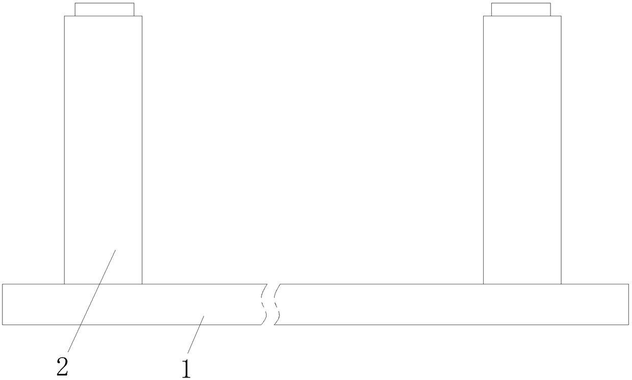
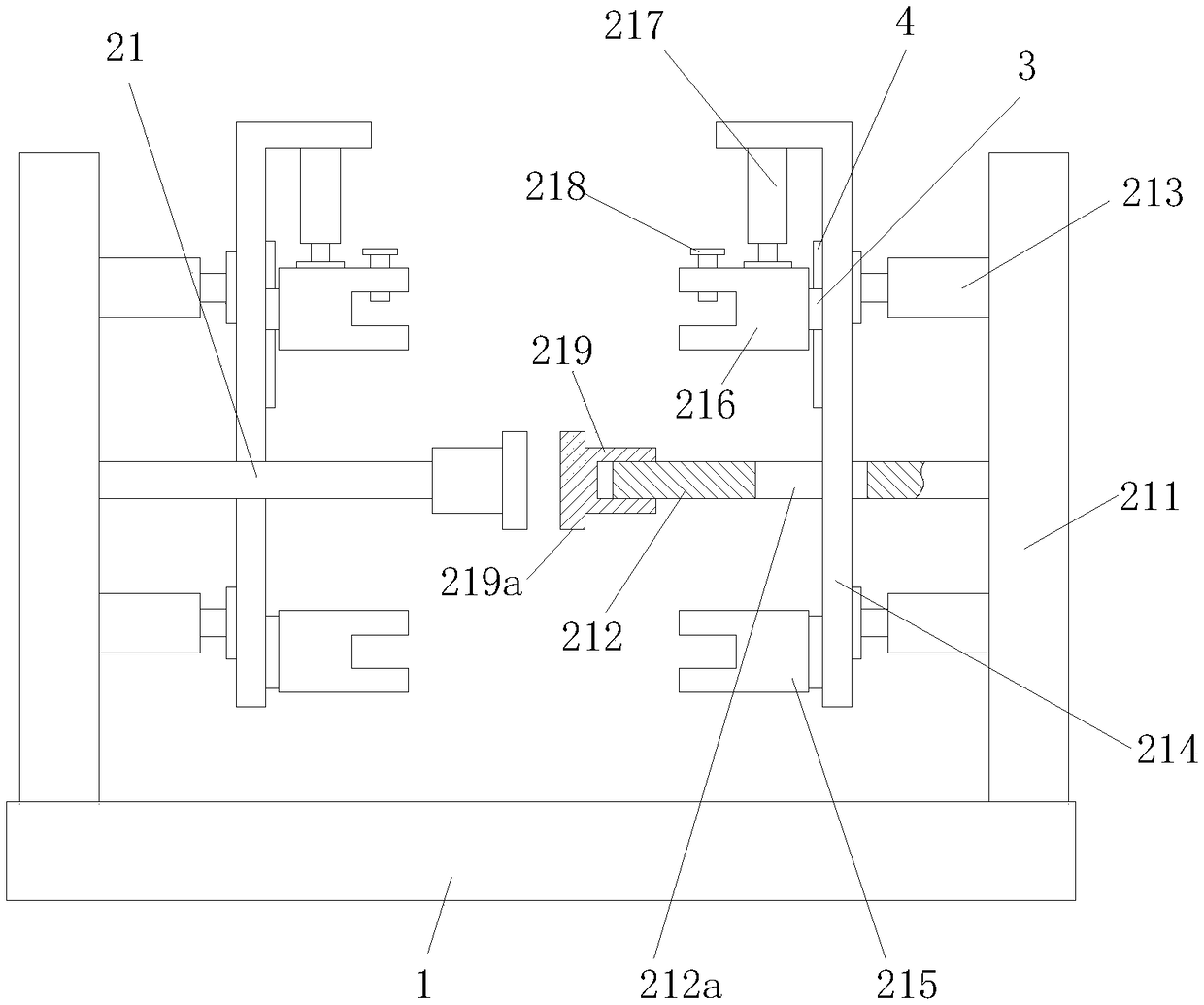
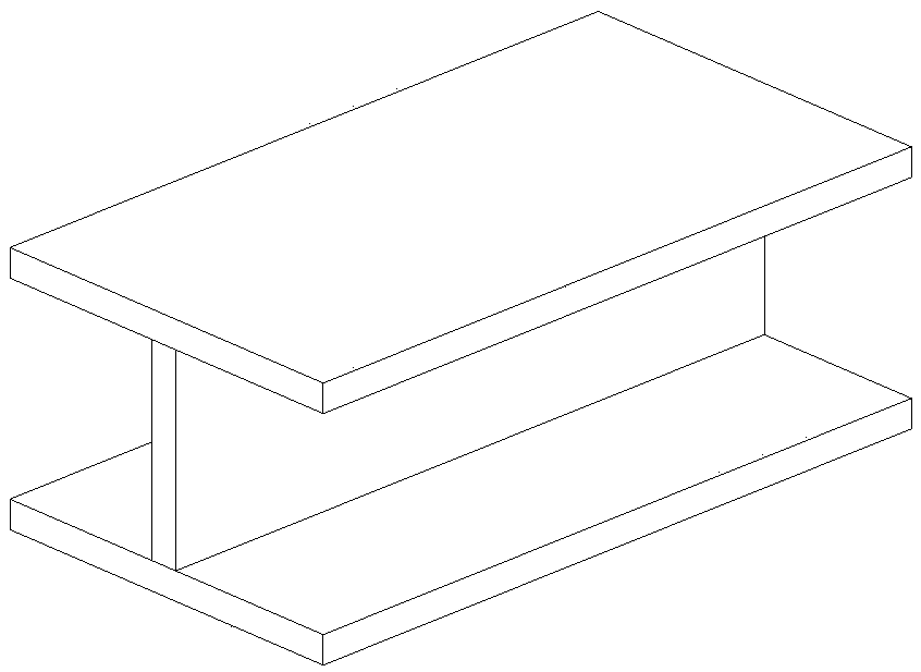
[0016] Such as Figure 1 to Figure 3 As shown, a fixing device for H-shaped steel splicing and forming includes a workbench 1, two fixing mechanisms 2 distributed along the length of the workbench 1, and the fixing mechanism 2 includes two positioning units 21 that are symmetrically arranged forward and backward;

[0017] The positioning unit 21 includes a vertical plate 211, a positioning rod 212 fixed in the middle of the vertical plate 211, a horizontal push cylinder 213 fixed on the vertical plate 211, a vertical plate 214 connected to the output end of the horizontal push cylinder 213, A lower U-shaped clamping block 215 on the plate 214, an upper U-shaped clamping block 216 vertically slidingly connected with the vertical plate 214, and a push-down cylinder 217 connected to the upper U-shap...


PUM


Abstract

The invention relates to a fixing device used for splicing forming of H-shaped steel. The fixing device comprises a workbench and two fixing mechanisms distributed in the length direction of the workbench. Each fixing mechanism comprises two positioning units which are arranged symmetric front and back. Each positioning unit comprises a vertical plate, a positioning rod fixed to the middle of thevertical plate, horizontal pushing air cylinders fixed to the vertical plate, an upright plate connected with the output ends of the horizontal pushing air cylinders, a lower U-shaped clamping block fixed to the upright plate, an upper U-shaped clamping block in vertical sliding connection with the upright plate, and a downward pushing air cylinder fixed to the upright plate, wherein the output end of the downward pushing air cylinder is connected with the upper U-shaped clamping block. The top of the upper U-shaped clamping block is in threaded connection with an adjustable bolt. The adjustable bolt is vertically arranged and can be screwed into a U-shaped port of the upper U-shaped clamping block. The free end of the positioning rod is in screw thread fit with a cylindrical sleeve. A pressing block is arranged on the cylindrical sleeve. According to the fixing device used for splicing forming of the H-shaped steel, all steel products used for splicing assembly of the H-shaped steel can be fixed and clamped, the positioning precision is high, the quality of the formed H-shaped steel is high, the labor intensity is effectively relieved, and the working efficiency is improved.

Description

technical field [0001] The invention relates to the technical field of mechanical devices, in particular to a fixing device for splicing and forming H-shaped steels. Background technique [0002] As we all know, H-shaped steel is an economical cross-section high-efficiency section with more optimized cross-sectional area distribution and more reasonable strength-to-weight ratio. It is named because its cross-section is the same as the English letter "H". Since all parts of the H-shaped steel are arranged at right angles, the H-shaped steel has the advantages of strong bending resistance in all directions, simple construction, cost saving and light structural weight, and has been widely used. Generally, H-shaped steel is assembled from three long pieces of steel into an H-shape and then welded. When splicing the steel, the workers will perform spot welding at the joints of each steel in advance, and finally perform full welding. However, this method requires manual positioni...

Claims


Application Information

Patent Timeline
IPC IPC(8): B23K37/04
CPCB23K37/0443
Inventor 程敬卿周乾坤薛卫昌
Owner WUHU DINGHENG MATERIAL TECH
Why Eureka
Try Eureka