Ultraviolet sterilizing device in alternating magnetic field environment

A technology of alternating magnetic field and sterilizing device, which is applied in the direction of light water/sewage treatment, water/sewage treatment, water/sludge/sewage treatment, etc. It can solve the problems of consumption, waste of electric energy, and heavy workload, and achieve easy use Effect

Pending Publication Date: 2018-12-21
黄鑫泉
View PDF6 Cites 2 Cited by
  • Summary
  • Abstract
  • Description
  • Claims
  • Application Information

AI Technical Summary

Problems solved by technology

[0003] In view of the deficiencies in the prior art, the purpose of the present invention is to provide an ultraviolet sterilizing device under an alternating magnetic field environment to solve the problem that the common ultraviolet sterilizing device used in the current technology is used for reinjection of oilfield produced water due to the large amount of produced water. The ultraviolet sterilizer needs continuous work, the workload is large, the load of the equipment is large, and it needs to consume more electric energy, so the cost of reinjection of produced water is also high, and the equipment cannot be determined according to the amount of water passing through the equipment. The size of the power of the ultraviolet lamp, the size of the power of the ultraviolet lamp does not match the size of the water flow, which affects the processing efficiency of the equipment and wastes electric energy

Method used


Image

  • Ultraviolet sterilizing device in alternating magnetic field environment
  • Ultraviolet sterilizing device in alternating magnetic field environment
  • Ultraviolet sterilizing device in alternating magnetic field environment

Examples


Embodiment Construction

[0022] In order to make the technical means, creative features, goals and effects achieved by the present invention easy to understand, the present invention will be further described below in conjunction with specific embodiments.

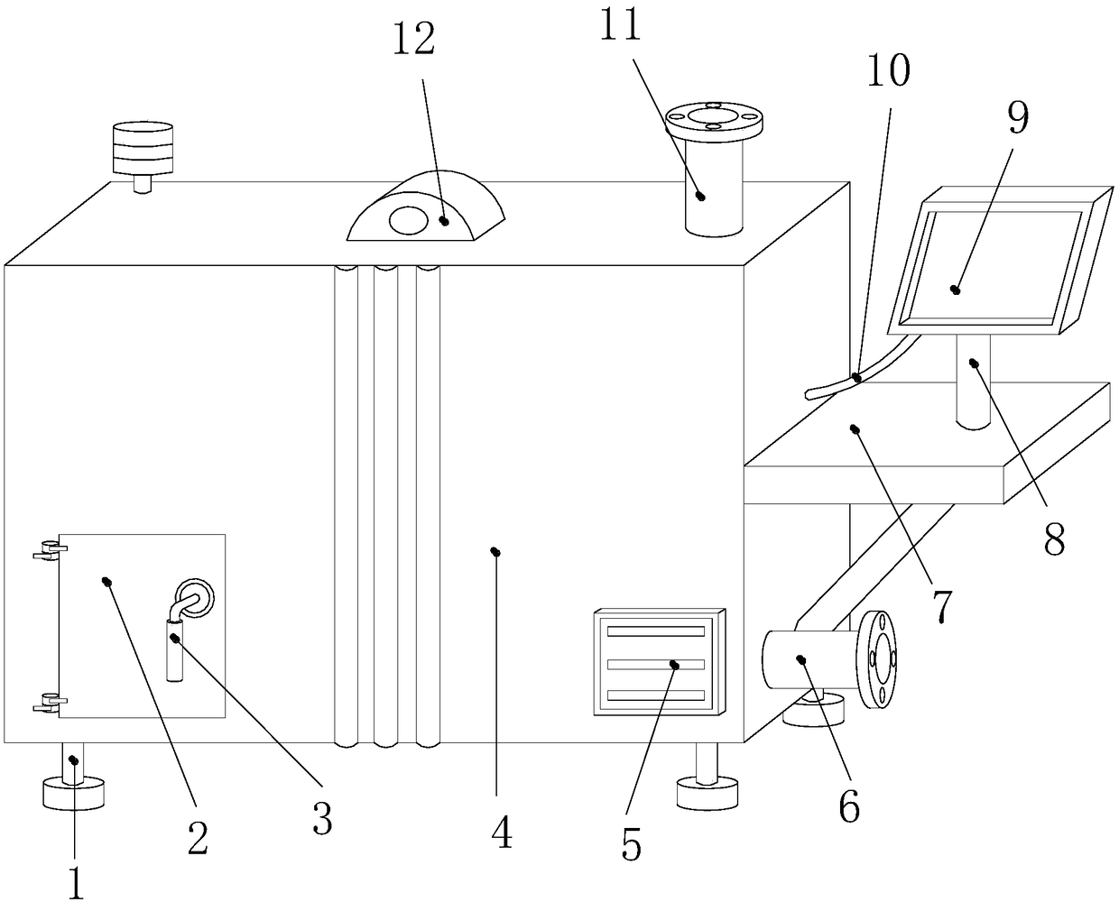
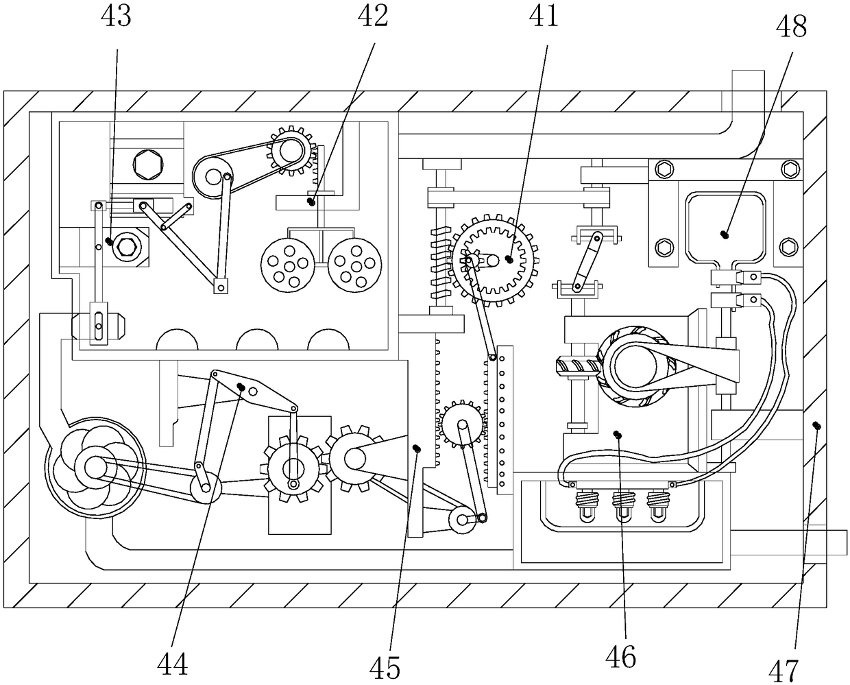
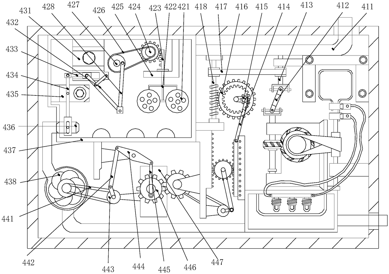
[0023] see Figure 1-Figure 4 , the present invention provides an ultraviolet sterilizing device in an alternating magnetic field environment: its structure includes a tripod 1, an opening and closing door 2, a handle 3, a magnetic generating device 4, a vent 5, a water outlet 6, a workbench 7, and a display Fixed rod 8, display 9, transmission wire 10, water inlet 11, hanging ring ear 12, said hanging ring ear 12 is welded on the center of the upper surface of magnetic generating device 4, and said water inlet 11 is embedded in magnetic generating device 4 The right end of the upper surface, the opening and closing door 2 is hinged on the left end of the front of the magnetic generating device 4, the handle 3 is embedded in the right end of the f...


PUM


Abstract

The invention discloses an ultraviolet sterilizing device in an alternating magnetic field environment. A structure of the ultraviolet sterilizing device comprises a foot stand, an opening-closing door, a handle, a magnetic-electric device, a ventilating port, a water outlet, a workbench, a display fixing rod, a display, a transmitting wire, a water inlet, and a hanging ring lug. The hanging ringlug is welded to a center of the upper surface of the magnetic-electric device. The water inlet is embedded in the right end of the upper surface of the magnetic-electric device. The opening-closing door is hinged to the left end of the front face of the magnetic-electric device. The handle is embedded in the right end of the front face of the opening-closing door. The ultraviolet sterilizing device is capable of, through installing the magnetic-electric device, automatically changing a revolving speed of a turbine according to a size of a water flow, and driving a coil to cut a magnetic induction line through the turbine, wherein a speed of cutting is rapider, and an electric current passing through the coil is larger, the electric current supplies power for an ultraviolet lamp, and powerof the ultraviolet lamp is automatically changed according to the size of the water flow, improving sterilizing efficiency of the device without wasting electric energy, automatically supplying power, saving energy and protecting the environment, and convenient to use.

Description

technical field [0001] The invention relates to an ultraviolet sterilizing device under an alternating magnetic field environment, which belongs to the field of ultraviolet rays and sterilizing devices. Background technique [0002] The ultraviolet germicidal lamp is actually a kind of low-pressure mercury lamp. The low-pressure mercury lamp emits ultraviolet light by being intensified by the lower mercury vapor pressure. The ultraviolet light of the appropriate wavelength can destroy the molecular structure of DNA or RNA in the cells of microorganisms, causing The death of growing cells and the death of regenerative cells can achieve the effect of sterilization and disinfection. At present, when the common ultraviolet sterilizing device is used to treat the reinjection of oilfield produced water, due to the large amount of produced water, the ultraviolet sterilizing device needs continuous work. The amount of water is large, the load of the equipment is large, and it needs ...

Claims


Application Information

Patent Timeline
Patent Type & Authority Applications(China)
IPC IPC(8): C02F1/32
CPCC02F1/32C02F2201/002C02F2201/007C02F2201/009C02F2201/32
Inventor 黄鑫泉
Owner 黄鑫泉
Why Eureka
Try Eureka