
Prefabricated floor slab and prefabricated floor slab mould

A floor slab and mold technology, applied in the field of prefabricated floor slabs and prefabricated floor slab moulds, can solve the problems of increased labor costs and assembly costs, high assembly costs, and large manpower consumption, so as to save labor costs and construction time, use flexibly, and reduce time cost effect

Pending Publication Date: 2018-12-21
李倩倩 +1
View PDF0 Cites 1 Cited by
  • Summary
  • Abstract
  • Description
  • Claims
  • Application Information

AI Technical Summary

Problems solved by technology

[0003] In the prefabricated building industry, most of the existing laminated slabs adopt the method of side reinforcement (reserved steel bars protruding from the head), while the methods of reinforcement in the prior art are usually divided into four-side reinforcement and two-side reinforcement. There are two kinds of ribs; although the laminated floors with these two methods of ribbing are good in stability after installation; however, due to the ribs on the four sides of the laminated floor or the ribs on both sides, it is necessary to avoid the side of the adjacent laminated floor during the assembly process. Reinforcement interacts with each other, requiring a lot of manpower to correct the reinforcement, and the assembly cost is high; at the same time, the laminated floor slab with reinforcement on four sides or reinforcement on both sides needs to consume too much material in the production process, and the manufacturing cost is high. Adjacent laminated floor slabs need to be replenished manually after installation, which further increases labor costs and assembly costs

Method used


Image

  • Prefabricated floor slab and prefabricated floor slab mould
  • Prefabricated floor slab and prefabricated floor slab mould
  • Prefabricated floor slab and prefabricated floor slab mould

Examples


Embodiment 1

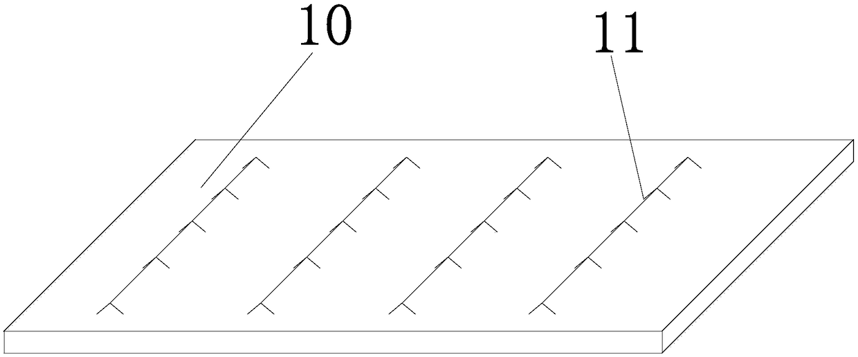
[0029] Such as figure 2 As shown, this embodiment provides a prefabricated floor slab, including a slab body and truss reinforcements arranged in the slab body; the lower chord of the truss reinforcement is buried in the slab body, and its upper chord is located in the post-cast concrete laminated layer, that is, the upper chord of the truss reinforcement is exposed Outside the upper surface of the slab, the post-cast concrete layer is the concrete layer cast on the slab during the on-site construction stage; in the actual production process, in order to increase the friction between the slab and the concrete layer, The upper surface of the slab body is a rough surface; when assembling the above prefabricated floor slab, place the prefabricated floor slab at a preset position, and then cast a concrete laminated layer on the upper surface of the slab body, thereby improving the tensile performance and crack resistance of the building Better performance and anti-seepage perform...

Embodiment 2

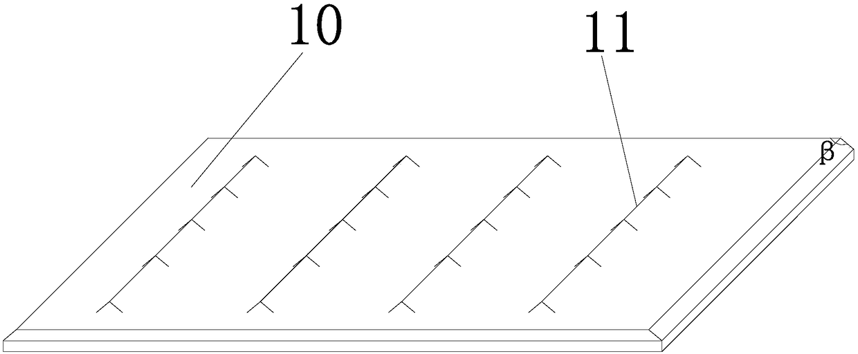
[0033] Such as figure 1 As shown, this embodiment provides a prefabricated floor slab, which includes a slab body and truss bars arranged in the slab body; the lower chord of the truss bars is embedded in the slab body, and its upper chord is located in the post-cast concrete laminated layer.

[0034] In this embodiment, the lower part of the plate body is a cuboid; the angle β between the side surface of the upper part of the plate body and its upper surface is not less than 90°, specifically, the angle β between two sides of the upper part of the plate body and its upper surface The included angle β is not less than 90°, thus corresponding to the inclined plane made by the folded edge of the above-mentioned prefabricated floor mold, which ensures that the building meets the mechanical requirements while reducing the rib surface.

[0035] This embodiment also provides a prefabricated floor mold for making the above-mentioned prefabricated floor, which includes a mold table, a...

Embodiment 3

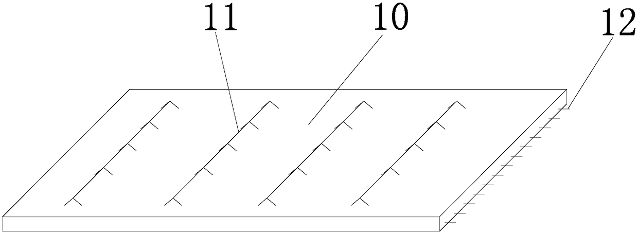
[0039] Such as image 3 As shown, this embodiment provides a prefabricated floor slab, which includes a slab body and truss bars arranged in the slab body; the lower chord of the truss bars is embedded in the slab body, and its upper chord is located in the post-cast concrete laminated layer. In this embodiment, a steel bar with one end protruding from the side of the plate body is arranged in the panel body. The steel bar can determine one or more sides of the current prefabricated floor according to the structure of the current building and the position of the current prefabricated floor in the building. The steel bar can make The connection between adjacent boards is more stable.

[0040] This embodiment also provides a prefabricated floor mold for making the above-mentioned prefabricated floor, which includes a mold table, and also includes a first side form, a second side form, and a third side mold located on the upper surface of the mold table and connected end to end. ...


PUM


Abstract

The invention belongs to the technical field of building profiles, and discloses a prefabricated floor slab and a prefabricated floor slab mould. The prefabricated floor slab comprises slab bodies andtruss reinforcing steel bars arranged in the slab bodies; the lower chords of the truss reinforcing steel bars are embedded in the slab bodies, and the upper chords of the truss reinforcing steel bars are located in a post-cast concrete laminated layers. The prefabricated floor slab mould comprises a mould platform, a first side mould body, a second side mould body, a third side mould body and afourth side mould body, and the first side mould body, the second side mould body, the third side mould body and the fourth side mould body comprise supporting surfaces and forming surfaces. The prefabricated floor slab and the prefabricated floor slab mould are high in practicability, the assembly processes and manufacturing cost during production of the prefabricated floor slab are reduced, themanual assembly time and the manufacturing time are saved, 60% of the on-site adjustment time can be saved, the labor cost of assembly and material supply is reduced, the construction time of assemblyand material supply is saved, the time cost, the labor cost and the manufacturing cost are reduced while it is ensured the requirements of construction mechanics are met, and the prefabricated floorslab and the prefabricated floor slab mould are suitable for application and popularization.

Description

technical field [0001] The invention belongs to the technical field of building profiles, and in particular relates to a prefabricated floor slab and a mold for the prefabricated floor slab. Background technique [0002] Prefabricated buildings refer to buildings assembled on site with prefabricated components. The advantage of this kind of building is that it can be constructed quickly, is less restricted by climatic conditions, saves labor and can improve the quality of construction. At present, domestic prefabricated building technology is becoming more and more mature, and laminated floor slabs are widely used as the main component. [0003] In the prefabricated building industry, most of the existing laminated slabs adopt the method of side reinforcement (reserved steel bars protruding from the head), while the methods of reinforcement in the prior art are usually divided into four-side reinforcement and two-side reinforcement. There are two kinds of ribs; although th...

Claims


Application Information

Patent Timeline
Patent Type & Authority Applications(China)
IPC IPC(8): E04B5/38B28B7/00
CPCE04B5/38B28B7/0029B28B7/0055
Inventor 李倩倩胡燕子
Owner 李倩倩
Learn More