Ultrasound wax prevention and viscosity reduction equipment for oil-well wellhead

An ultrasonic and viscosity-reducing technology, which is applied in wellbore/well parts, cleaning equipment, earthwork drilling and production, etc., can solve the problems of reducing production efficiency, increasing crude oil flow resistance, and corrosion of downhole equipment, so as to improve transmission efficiency and reduce viscosity. Thickness, anti-clogging effect

Active Publication Date: 2018-12-21
HEILONGJIANG LANDE ULTRASONIC TECH CO LTD
View PDF9 Cites 4 Cited by
  • Summary
  • Abstract
  • Description
  • Claims
  • Application Information

AI Technical Summary

Problems solved by technology

[0002] During the production of crude oil, during the flow of crude oil from the wellhead to the ground, as the temperature in the wellbore decreases, the viscosity of the crude oil increases. When the temperature drops to the waxing point of crude oil, wax deposition will form on the inner wall of the attached wellbore , increase the flow resistance of crude oil, reduce the production efficiency, increase the load of the pumping unit and the hot washing cycle of the oil well
However, for the exploitation of heavy oil and high-condensation oil, supporting processes such as steam injection, electric heating, chemical agent addition and thin oil mixing are required, which not only wastes energy, but also increases the difficulty of measures and processes, and causes serious corrosion to downhole equipment. , which greatly increases the cost of production operations

Method used


Image

  • Ultrasound wax prevention and viscosity reduction equipment for oil-well wellhead
  • Ultrasound wax prevention and viscosity reduction equipment for oil-well wellhead
  • Ultrasound wax prevention and viscosity reduction equipment for oil-well wellhead

Examples


specific Embodiment approach 1

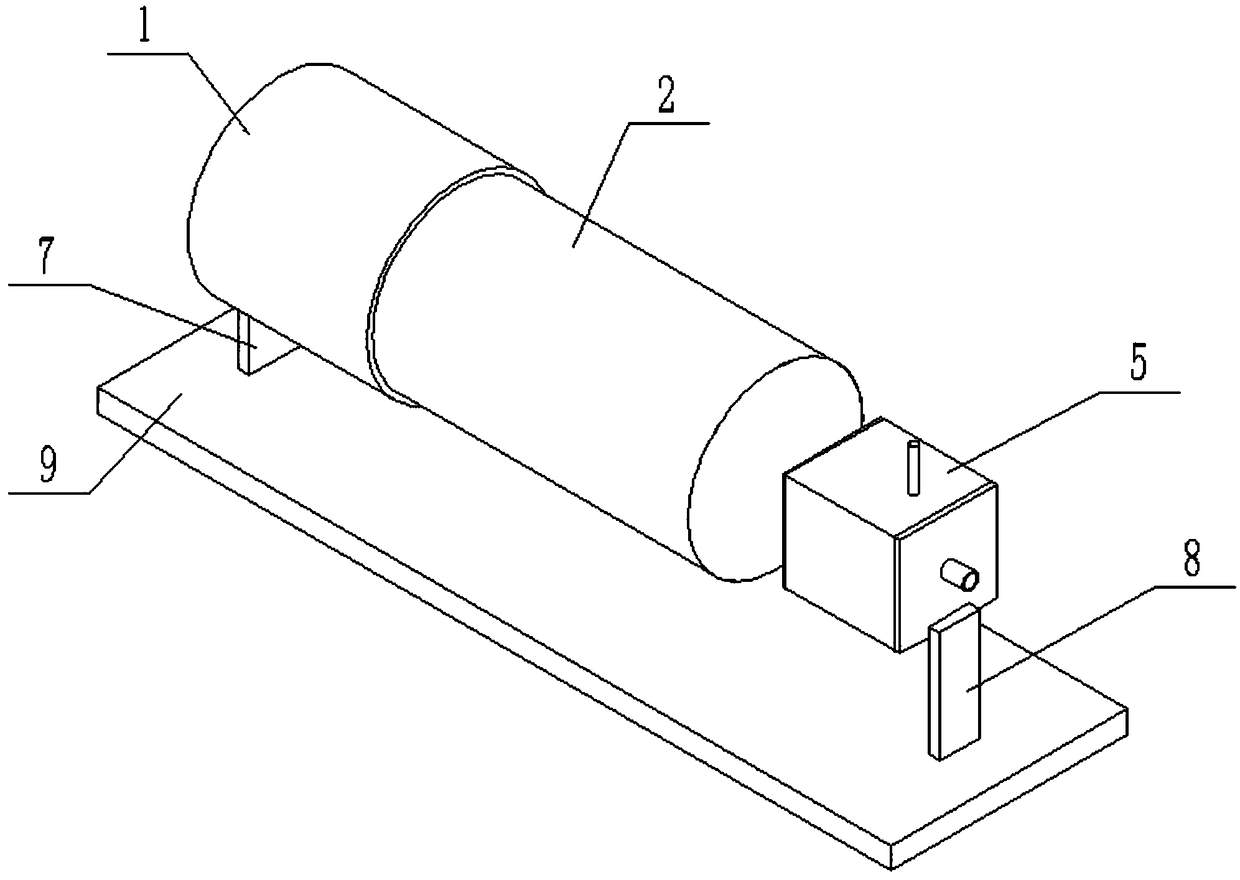
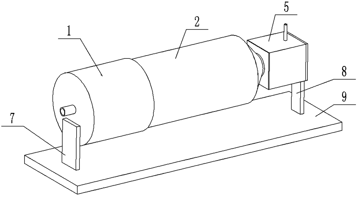
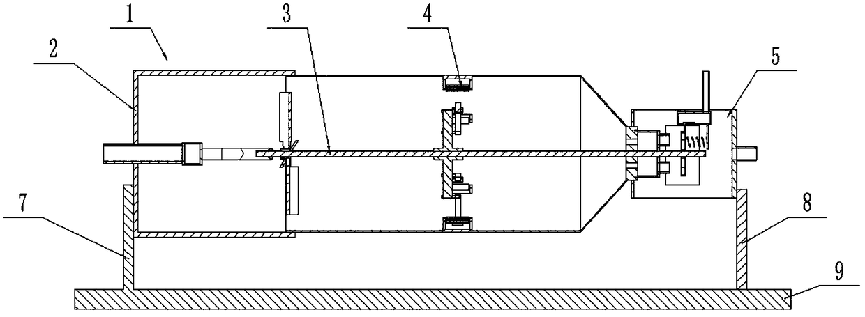
[0032] Such as Figure 1-14 As shown, the wellhead ultrasonic anti-wax and viscosity-reducing equipment for oil wells includes an oil inlet barrel 1, a stirring wax-proof barrel 2, a stirrer 3, multiple vibrators 4, an ultrasonic viscosity-reducing barrel 5, an ultrasonic transducer 6, a front bracket 7, and The rear bracket 8 and the base plate 9, the oil inlet cylinder 1 is fixedly connected to the front side of the top end of the base plate 9 through the front bracket 7; the rear end of the oil inlet cylinder 1 is hermetically connected and connected to the mixing wax-proof cylinder 2; The back end of the stirring wax-proof cylinder 2 is sealed and connected to the ultrasonic viscosity reducing cylinder 5; the agitator 3 is rotatably connected to the inner side of the stirring wax-proof cylinder 2; the inner surface of the stirring wax-proof cylinder 2 is evenly fixed and connected. A vibrator 4; the inner side of the ultrasonic viscosity reduction cylinder 5 is fixedly conn...

specific Embodiment approach 2

[0033] Such as Figure 1-14 As shown, the oil inlet tube 1 includes an oil inlet pipe 1-1, an oil inlet barrel body 1-2, an oil distribution box 1-3, and an injection oil pipe 1-4; the middle end of the oil inlet pipe 1-1 is connected in a sealed manner The front end of the oil inlet barrel body 1-2 and the rear end of the oil inlet pipe 1-1 are inserted into the inner side of the oil inlet barrel body 1-2. The rear end of the oil inlet pipe 1-1 is fixedly connected and connected to the oil distribution box 1-3. The rear end of the oil box 1-3 is fixedly connected to and communicated with two oppositely arranged injection oil pipes 1-4; the rear end of the oil inlet cylinder body 1-2 is sealedly connected and communicated with the stirring wax-proof cylinder 2. When the oil inlet cylinder 1 is in use, after the crude oil enters the oil separator box 1-3 through the oil inlet pipe 1-1, the crude oil is injected out through two injection oil pipes 1-4, and the crude oil is inject...

specific Embodiment approach 3

[0035] Such as Figure 1-14 As shown, the stirring wax-proof cylinder 2 includes a cylindrical cylinder 2-1, a conical cylinder 2-2 without a cone tip, and a short tube 2-3; the cylindrical cylinder 2-1, a cone without a cone tip The cylindrical body 2-2 and the short tube 2-3 are fixedly connected and communicated in sequence from front to back; the front end of the cylindrical body 2-1 is hermetically connected and communicated with the oil inlet cylinder body 1-2; The rear end is connected to the short tube 2-3 in a rotating fit; the rear end of the short tube 2-3 is fixedly connected and connected to the ultrasonic viscosity reducing cylinder 5.

[0036] The agitator 3 includes a stirring shaft 3-1, a rotating seat 3-2, a plurality of swirling inclined plates 3-3, a stirring and percussion mechanism 3-4, a rotating drum 3-5 hollowed out on the front side, and two jet straight Tube 3-6; The rotating seat 3-2 is fixedly connected to the front end of the stirring shaft 3-1, and...


PUM


Abstract

The invention relates to the field of petroleum exploitation equipment, in particular to ultrasound wax prevention and viscosity reduction equipment for an oil-well wellhead. The equipment includes anoil inlet cylinder, a stirring and wax prevention cylinder, a stirrer, multiple vibrators, an ultrasound viscosity reduction cylinder, ultrasonic transducers, a front bracket, a rear bracket and a base plate. The oil inlet cylinder is fixedly connected with the front side of the top of the base plate through the front bracket, the rear end of the oil inlet cylinder is sealingly connected and communicated with the stirring and wax prevention cylinder, the rear end of the stirring and wax prevention cylinder is sealingly connected and communicated with the ultrasound viscosity reduction cylinder, the stirrer is rotatably and cooperatedly connected with the inner side of the stirring and wax prevention cylinder, the inner side face of the stirring and wax prevention cylinder is uniformly andfixedly connected with several vibrators, and the inner side of the ultrasound viscosity reduction cylinder is fixedly connected with the several ultrasonic transducers. The equipment can be used forjet-stream whirl, stirring and viscosity reduction, vibration crushing and ultrasonic wax prevention processes of crude oil, and can effectively prevent wax deposition in the extraction or transportation processes of the crude oil, the viscosity of the crude oil is reduced and the transportation efficiency is easily improved.

Description

Technical field [0001] The invention relates to the field of oil exploitation equipment, in particular to an oil well wellhead ultrasonic wax prevention and viscosity reduction equipment. Background technique [0002] In the production of crude oil, when the crude oil flows from the wellhead to the ground, as the temperature in the wellbore decreases, the viscosity of the crude oil increases. When the temperature drops to the waxing point of the crude oil, wax deposition will form on the inner wall of the attached wellbore. , Which increases the flow resistance of crude oil, reduces the extraction efficiency, increases the load of the pumping unit and the hot wash cycle of the oil well. However, the exploitation of heavy oil and high pour-point oil requires steam injection, electric heating, chemical addition and thin oil mixing, which not only wastes energy, increases the difficulty of the measures and processes, but also causes serious corrosion to downhole equipment , Which g...

Claims


Application Information

Patent Timeline
Patent Type & Authority Applications(China)
IPC IPC(8): E21B37/00
CPCE21B37/00
Inventor 赵宪忠孙闯葛继海祝金磊迟毅
Owner HEILONGJIANG LANDE ULTRASONIC TECH CO LTD
Why Eureka
Try Eureka