Wind-driven generator yaw device with locking function

A wind turbine and yaw technology, which is applied in the directions of wind turbines, the configuration of installing/supporting wind turbines, and the control of wind turbines, can solve the problem that the yaw device of wind turbines does not have a locking function, etc. Efficiency, reliable and convenient operation

Inactive Publication Date: 2018-12-21
王帅
View PDF4 Cites 3 Cited by
  • Summary
  • Abstract
  • Description
  • Claims
  • Application Information

AI Technical Summary

Problems solved by technology

[0003] The purpose of the present invention is to provide a wind turbine yaw device with locking, which has the advantage of locking function and solves the problem that the common wind generator yaw device does not have the locking function

Method used


Image

  • Wind-driven generator yaw device with locking function
  • Wind-driven generator yaw device with locking function

Examples


no. 1 approach

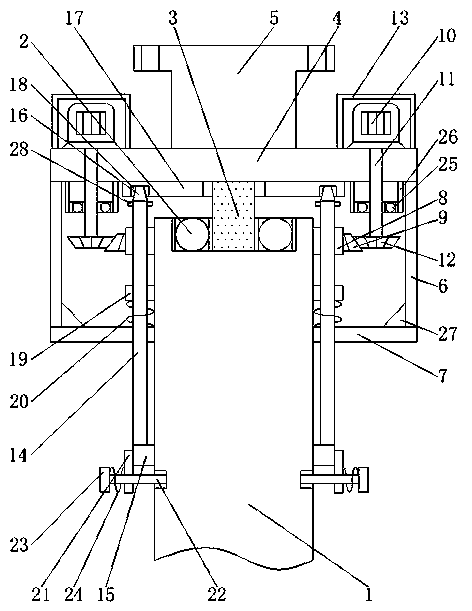
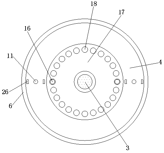
[0016] First implementation: see Figure 1-2 , a wind turbine yaw device with locking, comprising a tower bar 1, a support bearing 2 is fixedly connected to the groove at the top of the tower bar 1, and a rotating block 3 is fixedly connected to the inner wall of the support bearing 2, and the rotating The top of the block 3 runs through the supporting bearing 2 and extends to the outside. By setting the supporting bearing 2, the rotating block 3 can rotate without shaking. The top of the rotating block 3 is fixedly connected with the rotating plate 4, and the top of the rotating plate 4 A mounting block 5 is fixedly connected at the midpoint of the rotating plate 4, a rotating shell 6 is fixedly connected to the bottom of the rotating plate 4, a protective plate 7 is provided on the surface of the tower rod 1, the bottom of the rotating shell 6 is fixedly connected to the top of the protective plate 7, and the rotating The bottoms of the left and right sides of the inner wall...

no. 2 approach

[0019] The second embodiment: a wind turbine yaw device with locking, including a tower rod 1, a support bearing 2 is fixedly connected in the groove at the top of the tower rod 1, and a support bearing 2 is fixed on the inner wall of the support bearing 2 A rotating block 3 is fixedly connected, the top of the rotating block 3 runs through the supporting bearing 2 and extends to the outside, the top of the rotating block 3 is fixedly connected with a rotating plate 4, and the midpoint of the top of the rotating plate 4 is fixedly connected There is a mounting block 5, the bottom of the rotating plate 4 is fixedly connected with a rotating shell 6, the surface of the tower bar 1 is provided with a protective plate 7, and the bottom of the rotating shell 6 is fixedly connected with the top of the protective plate 7, so The surface of the tower rod 1 and the inside of the rotating shell 6 are fixedly connected with an annular plate 8, the surface of the annular plate 8 is fixedly c...


PUM


Abstract

The invention discloses a wind-driven generator yaw device with a locking function. The wind-driven generator yaw device comprises a tower frame rod, a supporting bearing is fixedly connected in a groove in the top of the tower frame rod, a rotating block is fixedly connected to the inner wall of the supporting bearing, the top of the rotating block penetrates through the supporting bearing and extends to the outside of the supporting bearing, a rotating plate is fixedly connected to the top of the rotating block, a mounting block is fixedly connected to the middle point of the top of the rotating plate, and a rotating shell is fixedly connected to the bottom of the rotating plate. According to the wind-driven generator yaw device with the locking function, a protection plate, limiting rods, a movable ring, limiting blocks, a limiting ring, limiting grooves, a movable plate, first springs, vertical plates, transverse rods, baffle plates and second springs cooperate with one another, sothat the wind-driven generator yaw device has the locking function, the yaw device can be conveniently limited by a worker, the situation that a fan blade of a wind-driven generator deviates from a set angle due to the influence of external force is avoided, the power generation efficiency of the wind-driven generator is improved, and great convenience is brought to a user.

Description

technical field [0001] The invention relates to the technical field of wind-driven generator yaw, in particular to a wind-driven generator yaw device with locking. Background technique [0002] The wind turbine yaw device, also known as the wind-facing device, is a part of the wind turbine nacelle. Its function is to quickly and smoothly align the wind direction when the direction of the wind speed vector changes, so that the wind rotor can obtain the maximum wind energy. The tail rudder is often used to face the wind, and the tail is installed on the tail boom parallel to or at a certain angle with the axis of the wind rotor. In order to avoid the influence of the wake, the tail can also be upturned and installed at a higher position. The common wind turbine The yaw device does not have a locking function. When the wind turbine rotor is rotated to the required angle, it is not convenient for the staff to limit the yaw device. The wind turbine rotor may deviate from the sett...

Claims


Application Information

Patent Timeline
Patent Type & Authority Applications(China)
IPC IPC(8): F03D7/02F03D13/20F03D80/00F03D80/70
CPCF03D7/0204F03D13/20F03D80/00F03D80/70F05B2270/329Y02E10/72Y02E10/728
Inventor 王帅
Owner 王帅
Why Eureka
Try Eureka