Supercharge Your Innovation With Domain-Expert AI Agents!

Magnetic levitation bearing structure and magnetic levitation motor

A technology of magnetic suspension bearing and clamping structure, which is applied to magnetic bearings, bearings, shafts and bearings, etc., can solve the problem that the interference between the shell and the radial ring cannot be satisfied, affect the reliability of the magnetic suspension bearing structure, and affect the coaxiality of the magnetic suspension assembly. Accuracy and other issues, to avoid multiple disassembly and assembly, reduce disturbance, reduce the amplitude and intensity of high-frequency vibration

Pending Publication Date: 2018-12-21
GREE ELECTRIC APPLIANCES INC +1
View PDF0 Cites 0 Cited by
  • Summary
  • Abstract
  • Description
  • Claims
  • Application Information

AI Technical Summary

Problems solved by technology

Existing known a kind of magnetic suspension radial bearing structure (as figure 1 ), including: stator winding, stator core, radial ring and housing, the housing and the radial ring are in an interference fit state, but the hardness of the housing is lower than that of the radial ring, when the housing shrink fit After matching or multiple disassembly and assembly, when the shell is plastically deformed, the interference between the shell and the radial ring cannot be satisfied, which affects the coaxial accuracy of the magnetic levitation assembly, is not conducive to the suspension control of the rotor, and then affects the structure of the magnetic levitation bearing. reliability

Method used


Image

  • Magnetic levitation bearing structure and magnetic levitation motor
  • Magnetic levitation bearing structure and magnetic levitation motor
  • Magnetic levitation bearing structure and magnetic levitation motor

Examples


Embodiment Construction

[0027] In order to make the object, technical solution and advantages of the present invention clearer, the present invention will be further described in detail below in conjunction with the accompanying drawings and embodiments. It should be understood that the specific embodiments described here are only used to explain the present invention, not to limit the present invention.

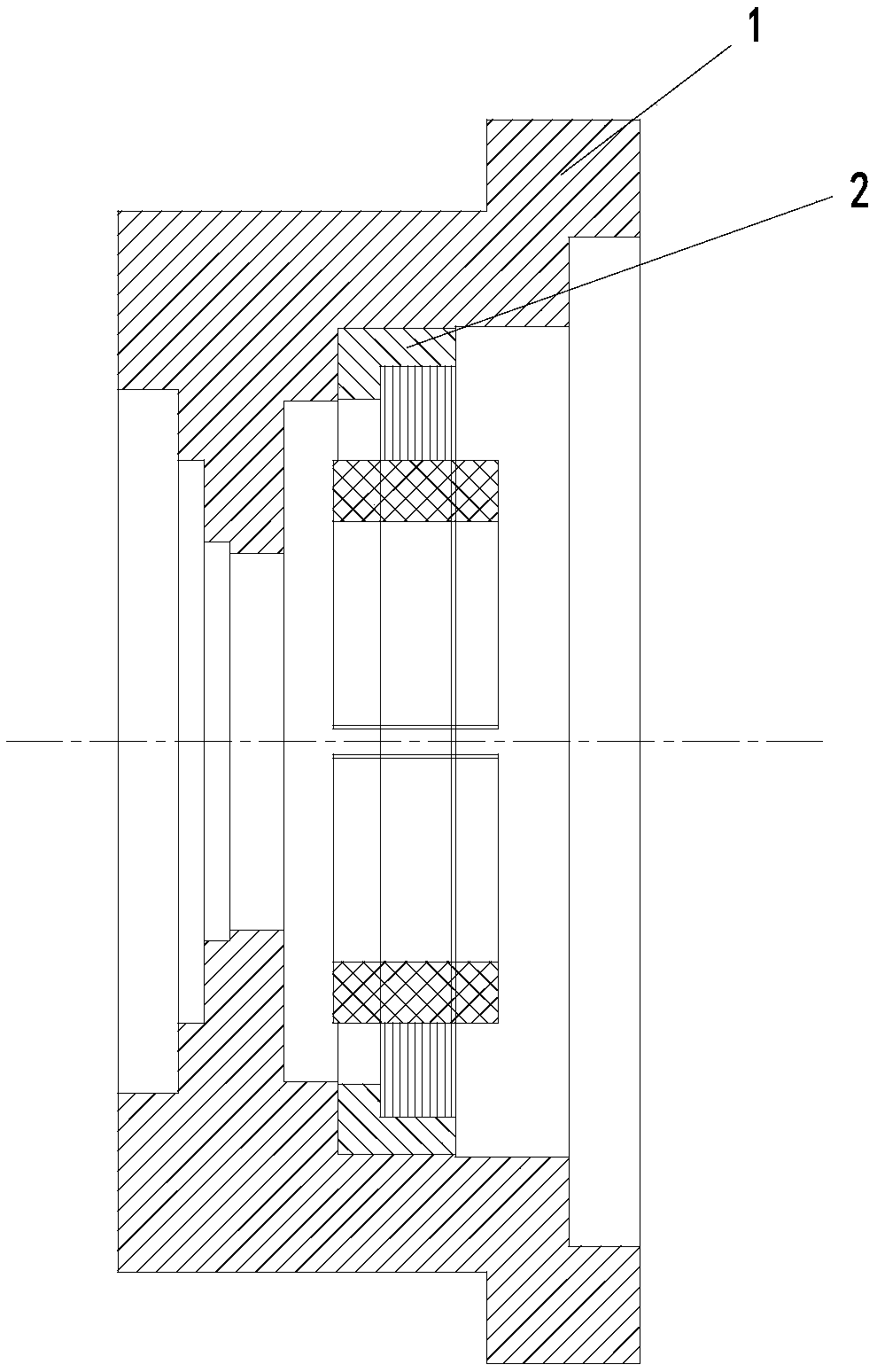
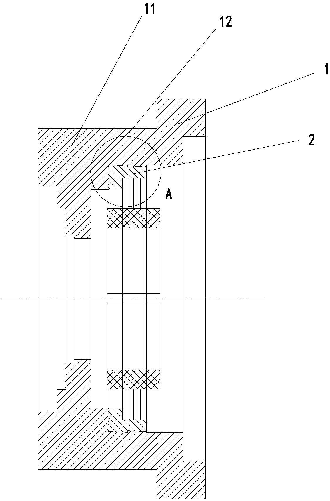
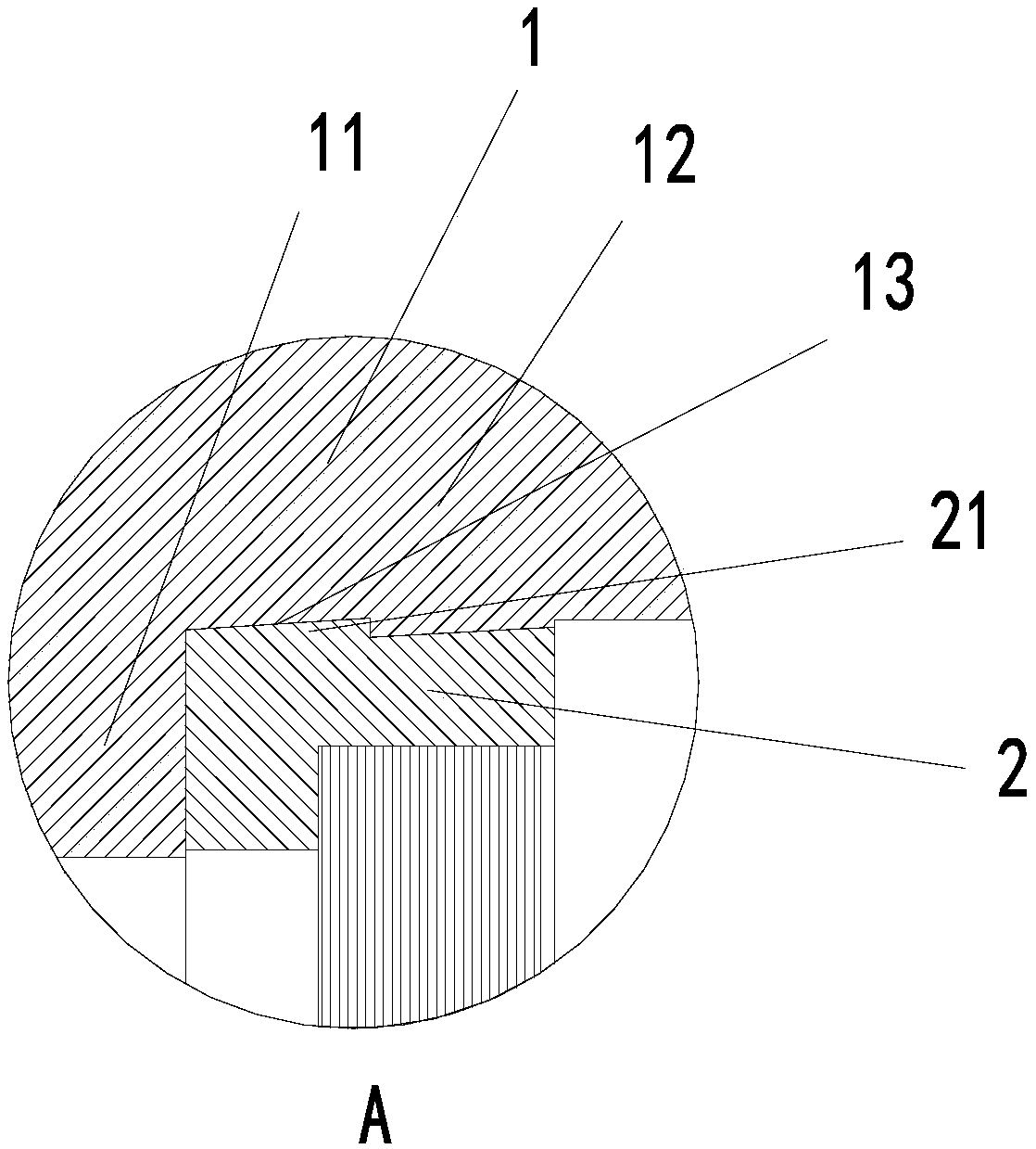
[0028] Magnetic levitation application products are ultra-high-speed machines. The magnetic levitation bearing is its key component. Once the magnetic levitation system breaks down, the magnetic levitation product will not be able to start levitation and cannot operate normally, resulting in production loss. The position limitation and fixation by positive fit cannot satisfy the effective position limitation and fixation of the casing 1 and the radial ring 2 under the condition of temperature rise or deformation, and thus cannot satisfy the reliability of the magnetic suspension bearing.

[0029] ...


PUM


Abstract

The invention provides a magnetic levitation bearing structure and a magnetic levitation motor. The magnetic levitation bearing structure comprises a shell and a radial ring. The peripheral side of the radial ring is sleeved with the shell, and a clamping structure is formed between the side faces, attached to each other, of the shell and the radial ring. According to the magnetic levitation bearing structure and the magnetic levitation motor, interference and limiting fit between the shell and the radial ring in the axial direction is achieved while interference fit between the inner side face of the shell and the peripheral side of the radial ring is ensured, so that the small-displacement high-frequency vibration amplitude and intensity are effectively reduced, disturbance of a rotor toa spindle is reduced, and the problem that the radial ring, a stator core and the shell are separated from one another is effectively solved; and it can be ensured that the radial ring is fixed to aspecific position of the shell under a designed temperature rise condition when the shell, the radial ring and the stator are made from different materials having different linear thermal expansion coefficients, so that a separation prevention effect is achieved, and the product reliability is effectively improved.

Description

technical field [0001] The invention relates to the technical field of magnetic suspension bearing processing, in particular to a magnetic suspension bearing structure and a magnetic suspension motor. Background technique [0002] Magnetic suspension bearings use magnetic force to suspend the rotor in the air, so that there is no mechanical contact between the rotor and the stator. Existing known a kind of magnetic suspension radial bearing structure (as figure 1 ), including: stator winding, stator core, radial ring and housing, the housing and the radial ring are in an interference fit state, but the hardness of the housing is lower than that of the radial ring, when the housing shrink fit After matching or multiple disassembly and assembly, when the shell is plastically deformed, the interference between the shell and the radial ring cannot be satisfied, which affects the coaxial accuracy of the magnetic levitation assembly, is not conducive to the suspension control of ...

Claims


Application Information

Patent Timeline
Patent Type & Authority Applications(China)
IPC IPC(8): F16C32/04
CPCF16C32/044F16C2380/26
Inventor 伍尚权王周叶龚敏周成海龙胜民黄积光张芳
Owner GREE ELECTRIC APPLIANCES INC
Features
  • R&D
  • Intellectual Property
  • Life Sciences
  • Materials
  • Tech Scout
  • Unparalleled Data Quality
  • Higher Quality Content
  • 60% Fewer Hallucinations
Learn More