Compound PWM control method of high speed switching valve

A technology of high-speed switching valves and control methods, which is applied in the direction of control valves, air release valves, brakes, valve details, etc., can solve the problems of not reducing the delay time of the valve core, being unable to adapt to changes in oil supply pressure, and difficult implementation, etc., to achieve Low power loss, accelerated unloading time, and reduced off-time effects

Active Publication Date: 2018-12-21
NANJING UNIV OF AERONAUTICS & ASTRONAUTICS +1
View PDF5 Cites 19 Cited by
  • Summary
  • Abstract
  • Description
  • Claims
  • Application Information

AI Technical Summary

Problems solved by technology

In terms of research on multi-PWM control methods, Chinese patent CN105805392 discloses a control method for improving the response speed of high-speed switching solenoid valves. This invention reduces coil power consumption by controlling the PWM frequency and maintaining the duty cycle during the spool maintenance phase. However, this invention does not reduce the delay time of the spool, and the maintenance of the duty cycle is obtained through a large number of test data, which is difficult to implement and cannot adapt to the working conditions of the oil supply pressure change

Method used


Image

  • Compound PWM control method of high speed switching valve
  • Compound PWM control method of high speed switching valve
  • Compound PWM control method of high speed switching valve

Examples


Embodiment Construction

[0044] The following will clearly and completely describe the technical solutions in the embodiments of the present invention with reference to the accompanying drawings in the embodiments of the present invention. Obviously, the described embodiments are only some, not all, embodiments of the present invention. Based on the embodiments of the present invention, all other embodiments obtained by persons of ordinary skill in the art without making creative efforts belong to the protection scope of the present invention.

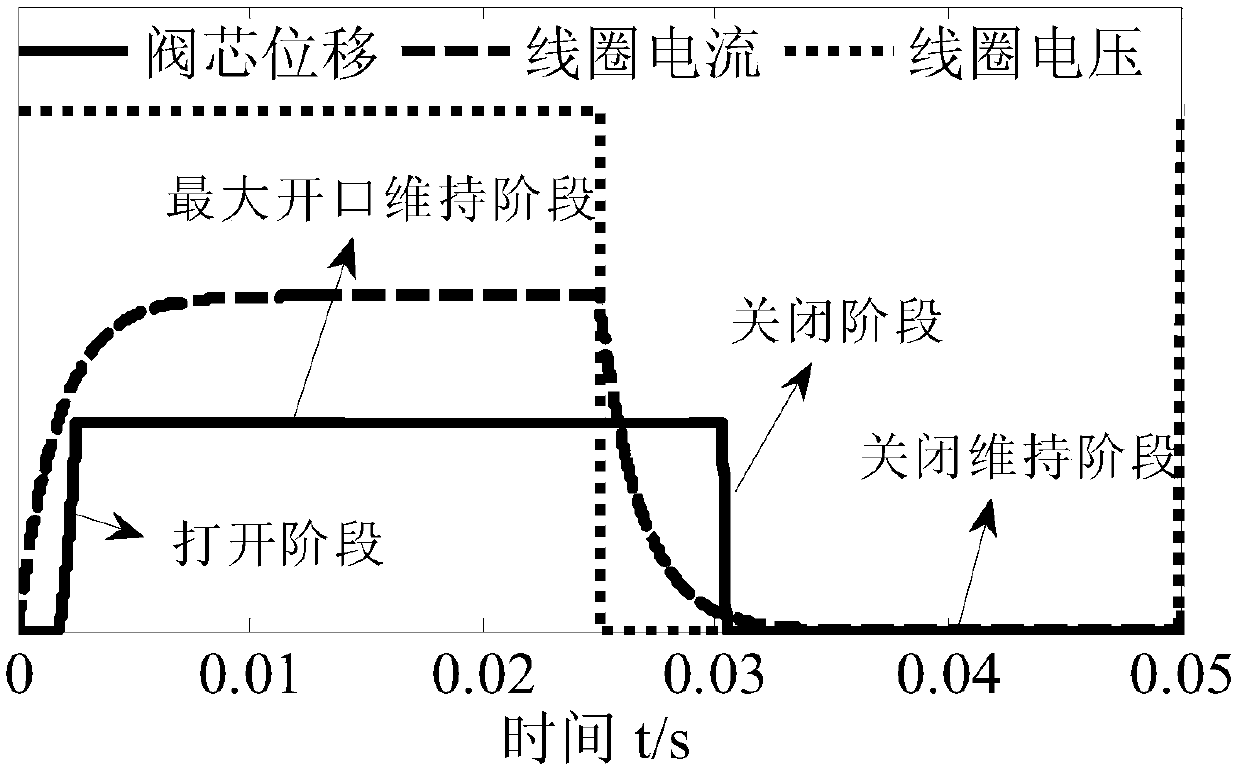
[0045] The invention discloses a compound PWM control method for a high-speed switching valve, which is characterized in that: the action process of the high-speed switching valve spool is defined as four stages, such as figure 1 As shown, it includes: the spool opening stage, the spool maximum opening maintenance stage, the spool closing stage and the spool closing maintenance stage. The spool opening stage is when the spool moves from the closed state to the...


PUM


Abstract

The invention discloses a compound PWM control method of a high-speed switching valve. The compound PWM control method of the high-speed switching valve is characterized in that the operation processof a valve core of the high-speed switching valve is defined as four stages which comprise a valve core opening stage, a valve core maximum opening maintaining stage, a valve core closing stage and avalve core closing and maintaining stage; in the valve core opening stage, the valve core is reliably opened by controlling the duty ratio of excitation PWM; during the valve core maximum opening maintaining stage, coil current is at an optimal value by controlling the duty ratio of high-frequency PWM, and the lowest power loss of a coil is ensured; and during the valve core closing stage, the coil current unloading is accelerated by controlling the duty ratio of reverse PWM, and valve core closing time is shortened. According to the compound PWM control method of the high-speed switching valve, a compound PWM signal is similar to a conventional PWM signal, the signal is only output through a hardware digital port, and the compound PWM control method of the high-speed switching valve has the advantages of high response, low power consumption and low cost.

Description

Technical field: [0001] The invention relates to a driving control method for a high-speed switching valve, in particular to a compound PWM control method for a high-speed switching valve Background technique: [0002] As the core component of the digital hydraulic system, the high-speed on-off valve is in the form of a poppet valve or a ball valve, and only works in the fully open or fully closed state. The main modulation methods include pulse code modulation (Pulse Code Modulation, PCM), pulse width Modulation (Pulse Width Modulation, PWM) and Pulse Number Modulation (Pulse Number Modulation, PNM). Compared with servo valves, high-speed switching valves have the advantages of no zero drift, no leakage and high reliability. They are used in aero-engines, aircraft brakes and automotive hydraulics. Braking and other fields have been applied to a certain extent. [0003] At present, the high-speed switching valve generally adopts a single PWM control method, which has the de...

Claims


Application Information

Patent Timeline
Patent Type & Authority Applications(China)
IPC IPC(8): F16K31/06B60T15/02
CPCB60T15/028F16K31/0675
Inventor 高强朱玉川罗樟
Owner NANJING UNIV OF AERONAUTICS & ASTRONAUTICS
Why Eureka
Try Eureka