A novel lightning protection overvoltage protection circuit and device
An overvoltage protection circuit, a new type of technology, applied in the field of power supply, can solve the problems of varistor voltage drop, overheating disconnector not responding in time, and rapid breakdown and short circuit speed.
- Summary
- Abstract
- Description
- Claims
- Application Information
AI Technical Summary
Problems solved by technology
Method used
Image
Examples
Embodiment 1
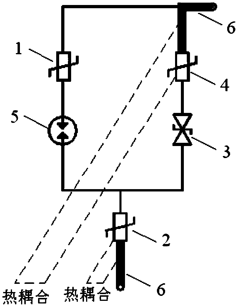
[0050] Such as figure 2 As shown, a new type of lightning protection overvoltage protection circuit includes a first varistor 1, a second varistor 2, a transient suppression diode 3, a positive temperature coefficient thermistor 4, and a gas discharge tube 5 and lead-out terminal 6, the first varistor sheet 1 is connected in series with the gas discharge tube 5, the positive temperature coefficient thermistor sheet 4 is connected in series with the transient suppression diode 3, and the two series branches After being connected in parallel, they are connected in series with the second piezoresistor 2 to form a single-port combined circuit, wherein the performance of the first piezoresistor 1 and the gas discharge tube 5 against surge impact is higher than that of the first piezoresistor. The performance of the second varistor sheet 2 to withstand surge impact.
[0051] The two lead-out terminals 6 of the single-port combined circuit are both low thermal resistance heat condu...
Embodiment 2
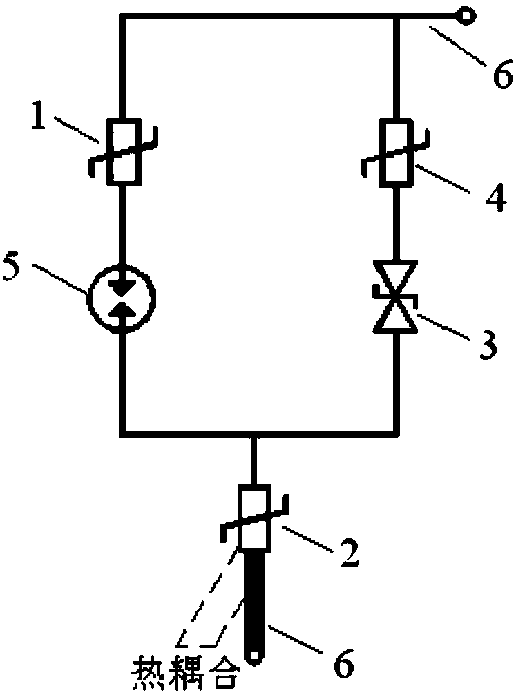
[0055] Such as image 3 As shown, the difference between this embodiment and Embodiment 1 is that only one of the two lead-out terminals 6 of the single-port combined circuit is a low thermal resistance heat conduction terminal, and the low thermal resistance heat conduction terminal is connected to the second varistor Sheets 2 are thermally coupled to each other.
Embodiment 3
[0057] The difference between this embodiment and Embodiment 1 is that only one of the two lead-out terminals 6 of the single-port combined circuit is a low thermal resistance heat conduction terminal, and the low thermal resistance heat conduction terminal is connected to the positive temperature coefficient thermistor sheet 4 Mutual thermal coupling (such as Figure 4 shown).
PUM
| Property | Measurement | Unit |
|---|---|---|
| Discharge current | aaaaa | aaaaa |
| Diameter | aaaaa | aaaaa |
Abstract
Description
Claims
Application Information
 - R&D
- Intellectual Property
- Life Sciences
- Materials
- Tech Scout
- Unparalleled Data Quality
- Higher Quality Content
- 60% Fewer Hallucinations
Browse by: Latest US Patents, China's latest patents, Technical Efficacy Thesaurus, Application Domain, Technology Topic, Popular Technical Reports.
© 2025 PatSnap. All rights reserved.Legal|Privacy policy|Modern Slavery Act Transparency Statement|Sitemap|About US| Contact US: help@patsnap.com


