In situ assembly of a bi-directional neural interface

An in-situ assembly, nerve technology, applied in spinal nerve electrodes, treatment, artificial respiration, etc., can solve problems such as non-positioning and use

Inactive Publication Date: 2018-12-21
GENERAL ELECTRIC CO
View PDF11 Cites 0 Cited by
  • Summary
  • Abstract
  • Description
  • Claims
  • Application Information

AI Technical Summary

Problems solved by technology

However, certain implanted devices designed to contact nerves, such as nerve cuffs, cannot be positioned and used without surgical dissection of the nerve

Method used


Image

  • In situ assembly of a bi-directional neural interface
  • In situ assembly of a bi-directional neural interface
  • In situ assembly of a bi-directional neural interface

Examples


Embodiment Construction

[0056] One or more specific embodiments will be described below. In an effort to provide a concise description of these embodiments, all features of an actual implementation are not described in the specification. It should be recognized that in the development of any such practical implementation, as in any engineering or design project, many implementation-specific decisions must be made to achieve the developer's specific objectives, such as compliance with system-related and business-related constraints, which may Vary from one embodiment to another. Furthermore, it should be appreciated that such a development effort might be complex and time consuming, but would nevertheless be a routine undertaking of design, fabrication, and manufacture for those having the benefit of this disclosure.

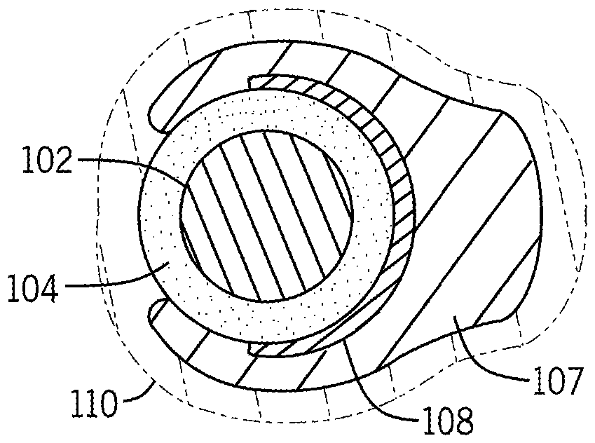
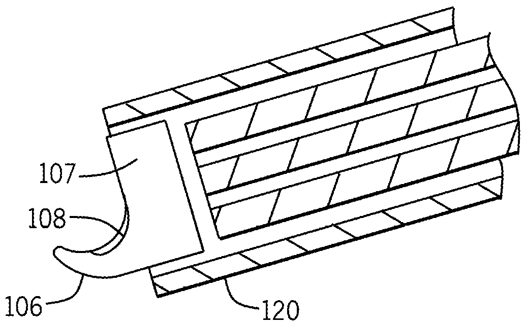
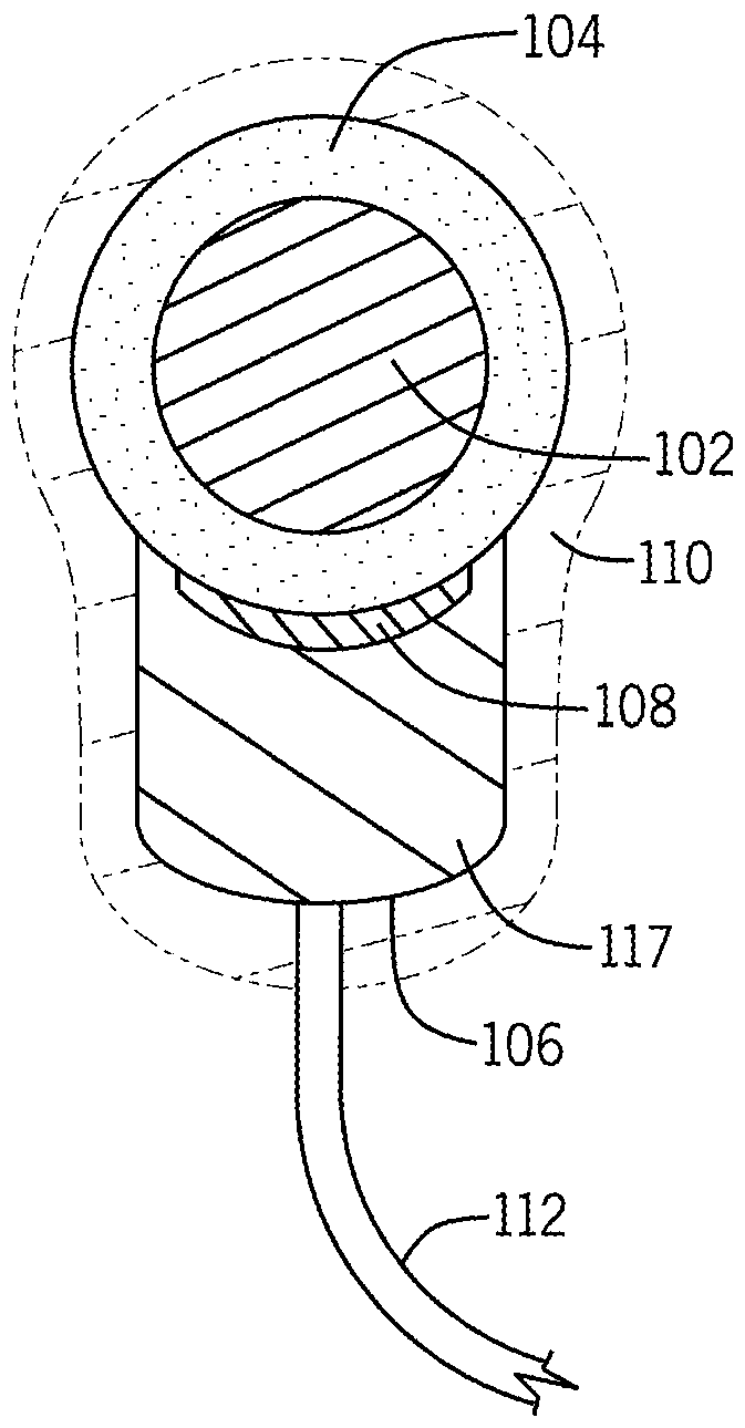
[0057] The present technology involves the generation of injectable bi-directional neural interfaces or neural cuffs capable of interfacing with peripheral nerves for directed stimulat...


PUM


Abstract

The subject matter of the present disclosure generally relates to a system for providing a bi-directional neural interface having an electrode configured to be positioned on a nerve; a substrate holding the electrode; a biocompatible insulator configured to electrically isolate the electrode when the electrode is positioned on the nerve, wherein the biocompatible insulator is formed in place aboutthe electrode; and a pulse generator configured to deliver energy pulses to the electrode.

Description

[0001] Cross References to Related Applications [0002] This application claims priority and benefit to US Provisional Application No. 62 / 308,009, filed March 14, 2016, the entire disclosure of which is hereby incorporated by reference. technical field [0003] The subject matter disclosed herein relates to the in situ assembly of injectable neural stimulator / recording devices, more specifically neural interfaces (eg, neural cuffs), and methods of stimulating and / or recording from nerves using such neural cuffs. Background technique [0004] Neurostimulation is used to treat a variety of clinical conditions. For example, electrical stimulation at various locations along the spinal cord is used to treat chronic back pain. Such treatments may be performed by devices that periodically generate electrical energy that is applied to tissue to activate certain nerve fibers, which in turn may result in reduced pain sensation. In the case of spinal cord stimulation, the stimulatin...

Claims


Application Information

Patent Timeline
Patent Type & Authority Applications(China)
IPC IPC(8): A61N1/05A61N1/36A61B5/04A61B17/00A61M5/19
CPCA61B17/00491A61M5/19A61N1/0556A61N1/0558A61N1/3605A61B2562/14A61B5/24A61B2560/0223A61L24/046A61L24/06A61L24/08A61L24/106A61L27/16A61L27/18A61N1/36128
Inventor J.M.阿瑟C.P.加利根C.M.普莱奥T-J.高
Owner GENERAL ELECTRIC CO
Why Eureka
Try Eureka