
Novel medical sterilization apparatus

A sterilizing device and a new type of technology, applied in water supply devices, sanitary equipment for toilets, heating, etc., can solve the problems of steam scalding of sterilized parts, inconvenient operation, waste of time, etc., and achieve good sterilization effect and sterilizing Thoroughly uniform and prevents the effect of beveling

Inactive Publication Date: 2018-12-25
自贡德西玛医疗设备有限公司
View PDF0 Cites 3 Cited by
  • Summary
  • Abstract
  • Description
  • Claims
  • Application Information

AI Technical Summary

Problems solved by technology

[0005] Aiming at the above-mentioned problems that are easy to be scalded by steam when taking out the sterilized parts, and the operation is inconvenient, the utensils are easy to break, etc., and it is time-consuming to wait until the temperature is low, the purpose of the present invention is to provide a new type of medical sterilization device

Method used


Image

  • Novel medical sterilization apparatus

Examples


Embodiment 1

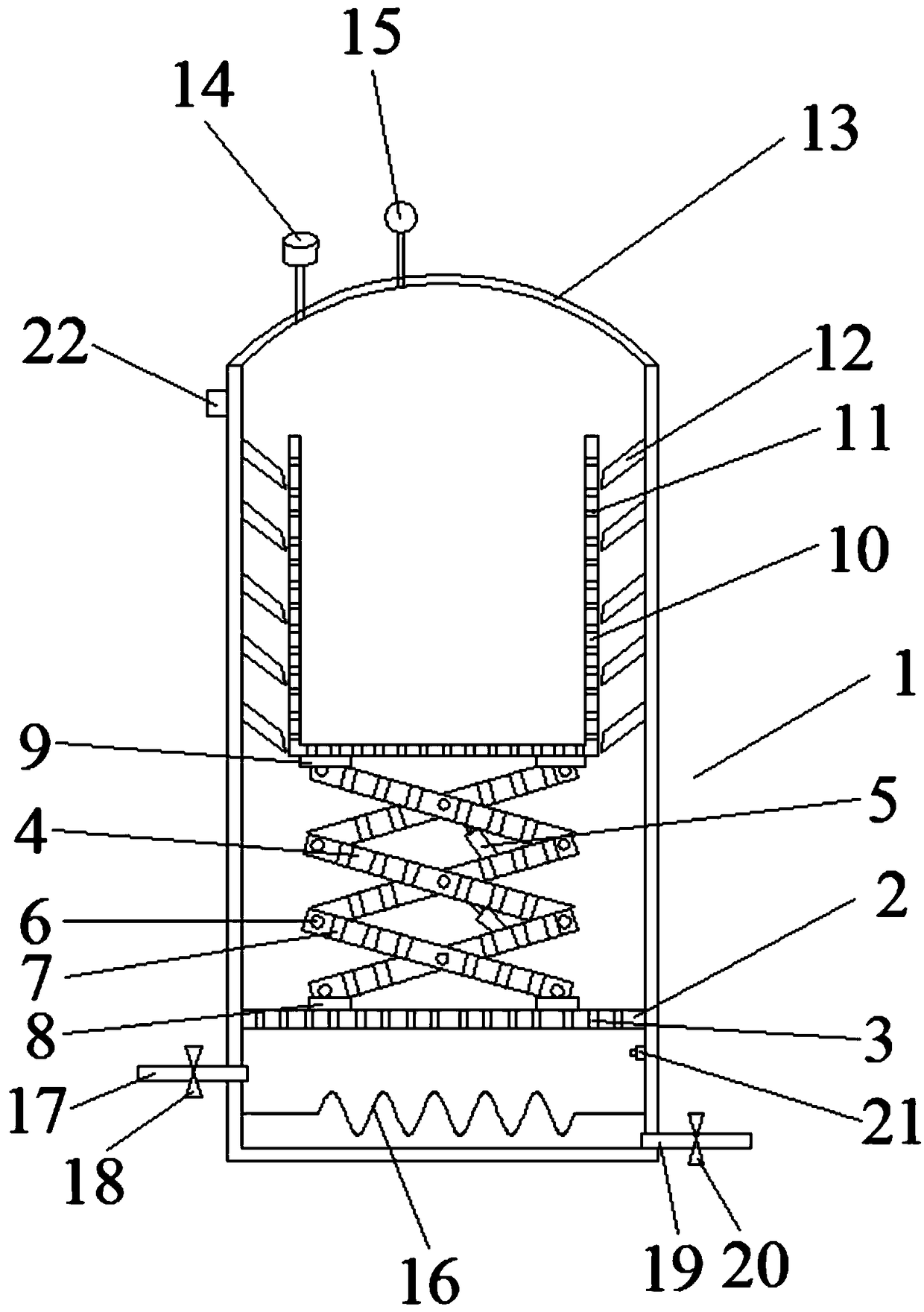
[0020] Such as figure 1 As shown, a new type of medical sterilization device includes a tank body 1, a support plate 2 is provided in the middle and lower part of the tank body 1, and the support plate 2 separates the tank body 1 into an upper sterilization chamber and a lower part. The steam generating chamber, the support plate 2 is provided with a plurality of first through holes 3, the upper part of the support plate 2 is provided with a lifting drive mechanism, and the upper part of the lifting drive mechanism is provided with a sterilization basket 10, the The body of the sterilization basket 10 is provided with a plurality of third through holes 11 , the top of the tank body 1 is provided with an openable tank cover 13 , and the tank cover 13 is provided with a safety valve 14 and an exhaust valve 15 .

[0021] Working principle: the tank cover 13 is opened, the lifting drive mechanism drives the sterilization basket 10 to rise, puts the medical glassware and other uten...

Embodiment 2

[0023] Based on Example 1, such as figure 1 As shown, the lifting drive mechanism includes a plurality of lifting rods 4 and connecting shafts 6, and the lifting rods 4 and the lifting rods 4 are cross-connected through the connecting shafts 6 to form a scissors shape. A hydraulic cylinder 5 is arranged between the lifting rods 4 .

[0024] The outer wall of the hydraulic cylinder 5 is provided with at least one layer of anti-rust layer to prevent the hydraulic cylinder 5 from rusting, and the contact part between the piston rod of the hydraulic cylinder 5 and the cylinder body is provided with a sealing ring to prevent steam from entering and damaging the hydraulic cylinder 5; the support is stable and the lifting is convenient.

Embodiment 3

[0026] Based on Example 1, such as figure 1 As shown, a first fixing member 8 is provided at the connection between the lifting rod 4 and the sterilization basket 10 , and a second fixing member 9 is provided at the connection between the lifting rod 4 and the support plate 2 .

[0027] Firmly fixed, high security.


PUM


Abstract

The invention discloses a novel medical sterilization apparatus and belongs to the technical field of medical equipment. The novel medical sterilization apparatus comprises a tank; a supporting plateprovided with a plurality of first through holes is arranged in the middle lower portion of the tank and divides the tank into an upper sterilization chamber and a lower steam generator chamber; a lifting drive mechanism is arranged on the upper side of the supporting plate, a sterilization basket is arranged on the lifting drive mechanism, and the body of the sterilization basket is provided witha plurality of third through holes; a cover for opening the tank is arranged at the top of the tank and is provided with a safety valve and an exhaust valve. With the arrangement of the steam generator chamber, the lifting drive mechanism and the sterilization basket, sterilized vessels can be picked conveniently, and work staff is protected against scalds; since the sterilization basket has suitable height, taking and placing of the vessels are facilitated, breakage of the vessels is avoided, and thus, time is saved for the work staff and work efficiency is improved.

Description

technical field [0001] The invention relates to the technical field of medical equipment, in particular to a novel medical sterilization device. Background technique [0002] In hospitals, most medical utensils must be sterilized. Metal objects such as tweezers, scissors, and scalpels need to be sterilized by burning, disinfectant, and ultraviolet disinfection. However, glassware such as beakers, petri dishes, and test tubes are sterilized The disinfection effect of the method is not good, and the high-pressure steam sterilization method is generally used. [0003] High-pressure steam sterilization can kill all microorganisms including spores, and is currently the best and most widely used sterilization method. This is due to the strong penetrability of pure water vapor. Proteins and protoplast colloids are easily denatured and solidified under hot and humid conditions, and the enzyme system is easily destroyed. Moreover, steam will condense into water when it enters the ce...

Claims


Application Information

Patent Timeline
Patent Type & Authority Applications(China)
IPC IPC(8): A61L2/07A61L2/26
CPCA61L2/07A61L2/26A61L2202/24
Inventor 邓述海
Owner 自贡德西玛医疗设备有限公司
Learn More