A tree branch cutting and crushing device for gardening

A technology for crushing devices and branches, applied in heating devices, lighting and heating equipment, grain processing, etc., can solve the problems of increased labor intensity and no walking function.

Inactive Publication Date: 2021-05-18
江苏健达交通工程有限公司
View PDF12 Cites 0 Cited by
  • Summary
  • Abstract
  • Description
  • Claims
  • Application Information

AI Technical Summary

Problems solved by technology

[0004] Although this patent can cut the branches, it can only cut the branches into branches of a certain degree of fragmentation. Some users need broken branches to burn fire and some users need branch chips for secondary processing into planks, and It cannot meet the needs of various groups of people; this utility model does not have the function of walking and needs to be carried manually, which increases the labor intensity for the practical users

Method used


Image

  • A tree branch cutting and crushing device for gardening
  • A tree branch cutting and crushing device for gardening
  • A tree branch cutting and crushing device for gardening

Examples


Embodiment 1

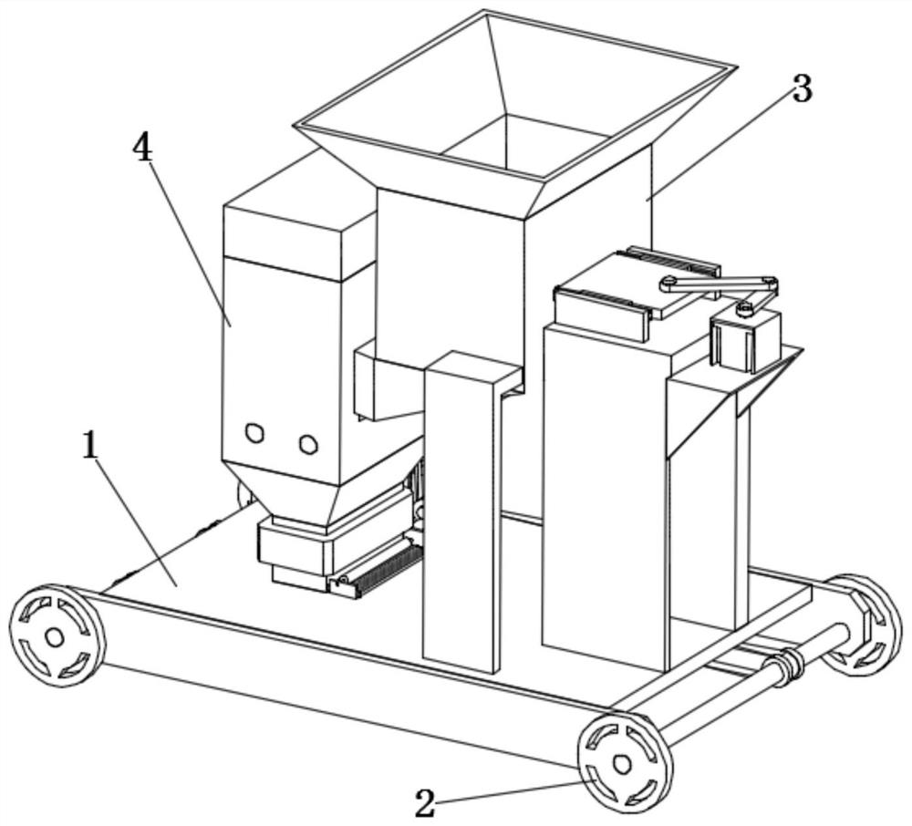
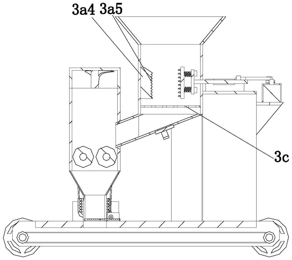
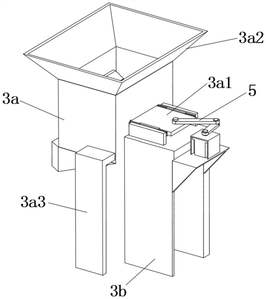
[0037] The present invention provides a kind of tree branch cutting and crushing device for gardens through improvement, such as Figure 1-Figure 10 As shown, it includes a supporting plate 1, a traveling assembly 2, a shearing assembly 3 and a crushing assembly 4, the traveling assembly 2 is located at the bottom of the supporting plate 1, and the shearing assembly 3 and the crushing assembly 4 are located at the top of the supporting plate 1 , the shearing assembly 3 includes a shearing cabinet 3a positioned directly above the supporting plate 1, a sliding plate 3a1 of a rectangular parallelepiped structure, and a drive assembly 5 for driving the sliding plate 3a1 to move in its own length direction, and the sliding plate 3a1 is located at Shear cabinet 3a side and with shear cabinet 3a sliding fit, described shear cabinet 3a top is provided with the feeding funnel 3a2 that is communicated with shear cabinet 3a, and described support plate 1 top is provided with two for The ...

Embodiment 2

[0049] The present invention provides another garden tree branch shearing and crushing device through improvement. Its general structure is the same as that of Embodiment 1, that is, it includes a supporting plate 1, a driving assembly 2, a shearing assembly 3 and a crushing assembly 4. Said driving assembly 2 is located at the bottom of the supporting plate 1, and the shearing assembly 3 and the crushing assembly 4 are located at the top of the supporting plate 1. The shearing assembly 3 includes a shearing cabinet 3a directly above the supporting plate 1, a The slide plate 3a1 and the driving assembly 5 used to drive the slide plate 3a1 to move in its own length direction, the slide plate 3a1 is located at the side of the shear cabinet 3a and is slidably matched with the shear cabinet 3a, and the top of the shear cabinet 3a is provided with The feeding funnel 3a2 that communicates with the shearing cabinet 3a, the top of the supporting plate 1 is provided with two L-shaped su...


PUM


Abstract

A tree branch shearing and crushing device for gardens provided by the present invention includes a supporting plate, a driving assembly, a shearing assembly and a crushing assembly, the shearing assembly includes a shearing cabinet, a sliding plate with a cuboid structure and a driving assembly, the sliding plate It is located next to the shearing cabinet and is slidingly matched with the shearing cabinet. The top of the shearing cabinet is provided with a feed funnel connected with the shearing cabinet. There are two L-shaped support plates on the top of the supporting plate. The crushing assembly includes a The crushing cabinet above the board, the crushing cabinet and the shearing cabinet are connected through the feed box. The beneficial effect of the present invention is that the cutting assembly and the crushing assembly can process the branches into broken branches and branch chips respectively to meet the needs of different users, the drying assembly can automatically dry the branch chips, and the driving assembly enables the device to Automatically walk to the desired location without manual handling.

Description

technical field [0001] The invention relates to the technical field of garden technology equipment, in particular to a tree branch cutting and crushing device for gardens. Background technique [0002] Landscaping construction units need to plant their own trees and flowers for greening. During the process of planting trees and flowers, the plants will drop old leaves and decompose them as natural fertilizers. However, in the process of artificial planting, this process needs to be accelerated, and the fallen leaves and dead branches will be broken. , mixing, and fermentation to form natural fertilizers to achieve the best results. At present, the branches are cut off manually. Generally, the branches are manually cut for fire, or the branches are manually crushed into twigs. The twigs can be used Secondary processing into wood boards, but manual work is inefficient, and long hours of work will also bring greater labor intensity to workers. [0003] The utility model patent...

Claims


Application Information

Patent Timeline
Patent Type & Authority Patents(China)
IPC IPC(8): B02C4/08B02C18/02B02C21/02B02C18/24B02C18/22B02C23/24F26B23/06
CPCB02C4/08B02C18/0084B02C18/02B02C18/2216B02C18/2291B02C18/24B02C21/026B02C23/24B02C2201/066F26B23/06
Inventor 顾舒夏
Owner 江苏健达交通工程有限公司
Why Eureka
Try Eureka