Continuous transverse laser cutter

A laser cutting machine, horizontal technology, used in laser welding equipment, welding/cutting auxiliary equipment, auxiliary devices, etc., can solve the problems of gas can not be effectively processed, cutting machine can not be continuously produced, etc., to achieve easy operation, strong applicability, The effect of reducing the interference of human factors

Active Publication Date: 2018-12-25
南通领翰激光科技有限公司
View PDF6 Cites 4 Cited by
  • Summary
  • Abstract
  • Description
  • Claims
  • Application Information

AI Technical Summary

Problems solved by technology

However, this kind of cutting machine cannot be produced continuously, and the gas generated cannot be effectively treated

Method used


Image

  • Continuous transverse laser cutter
  • Continuous transverse laser cutter
  • Continuous transverse laser cutter

Examples


Embodiment 1

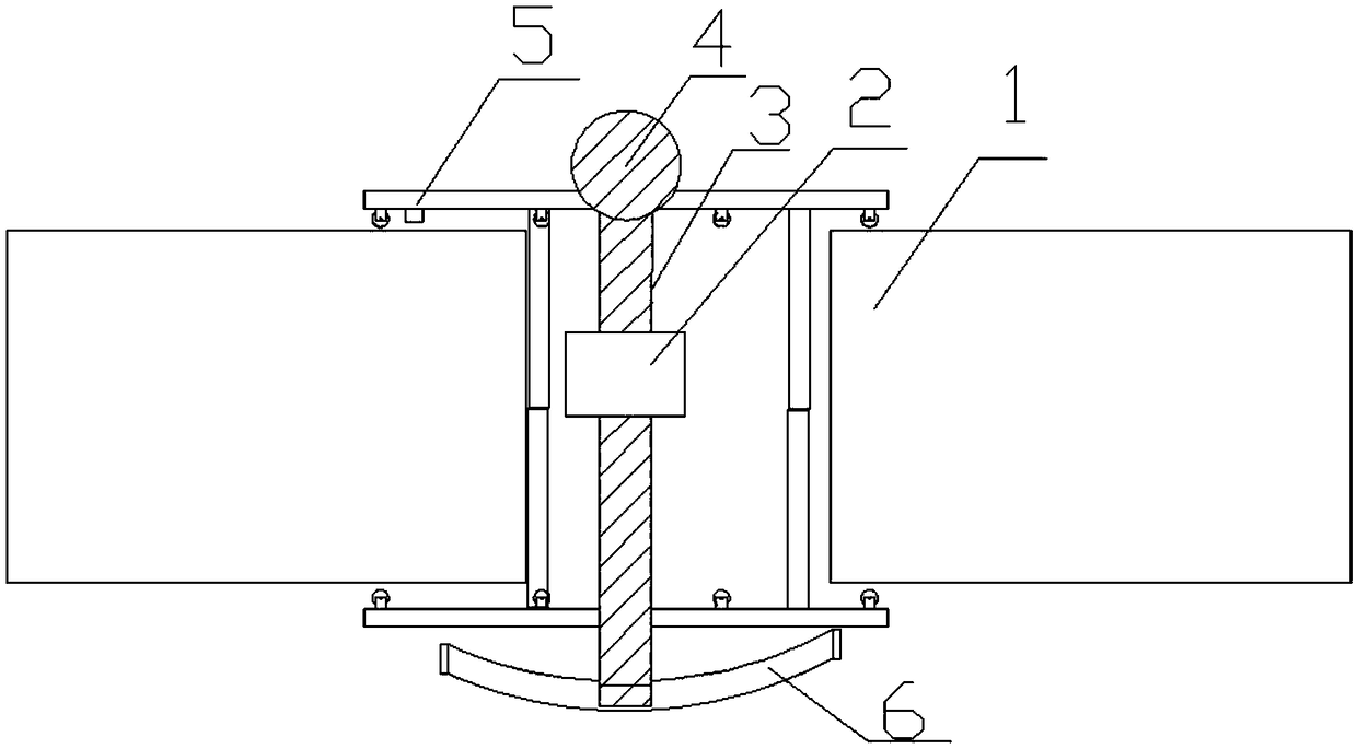
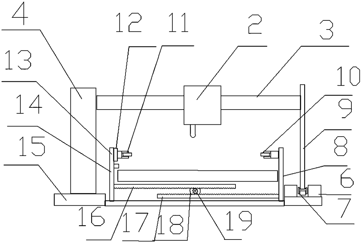
[0022] see Figure 1-3 , a continuous transverse laser cutting machine, including a base 15, a clamping device 5 and a cutting device 2. The base 15 is arranged between the conveyor belts 1 of the production line, and the conveyor belts 1 are used for conveying the products of the production line. The base 15 is horizontally fixed on the ground, and the upper surface of the base 15 is rotatably connected with a vertical support column 4 , and the support column 4 can rotate freely on the base 15 . The upper part of the support column 4 is fixedly connected with the left end of the horizontal slide bar 3 , the slide bar 3 is nested with a cutting device 2 , and the cutting device 2 can slide freely on the slide bar 3 . The right end of the slide bar 3 is fixedly connected to the top of the vertical vertical bar 9 , and the support column 4 and the vertical bar 9 support the slide bar 3 . The bottom of the vertical rod 9 is provided with a driving wheel 7, which is connected t...

Embodiment 2

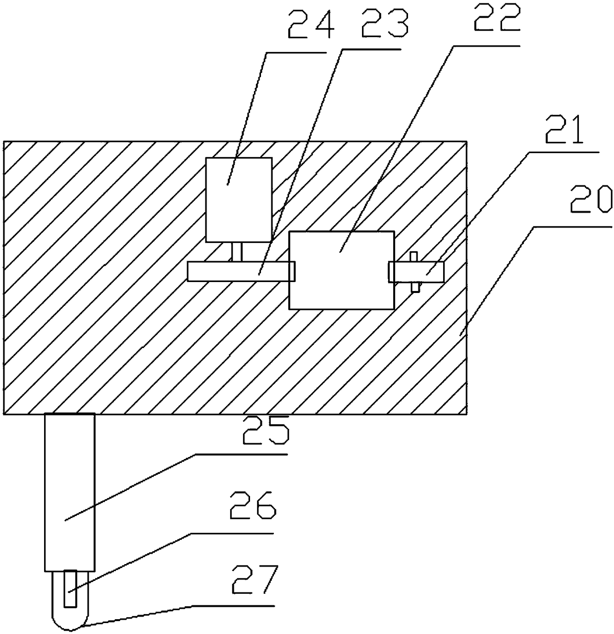
[0027] see Figure 4 , on the basis of Embodiment 1, the left side of the cutting rod 25 is provided with an air suction port 28 on the lower surface of the sliding block 20, the air suction port 28 is a trumpet-shaped structure with the opening downward, and the setting of the air suction port 28 is convenient The gas produced by cutting is sucked away to reduce the harmful gas harm to workers and environmental pollution. The suction port 28 communicates with the cyclone separator 30 provided inside the sliding block 20 through the air pipe 29, and the gas sucked through the suction port 28 enters the cyclone separator 30, and separates the particles and impurities inside the gas. The gas outlet of the cyclone separator 30 is connected to the adsorption layer 31 and the air pump 32 in sequence, and the adsorption layer 31 adsorbs and filters harmful gases in the gas.


PUM


Abstract

The invention relates to the technical field of cutting, and particularly discloses a continuous transverse laser cutter. The cutter comprises a base. A vertical supporting column is rotationally connected to the upper surface of the base. The upper portion of the supporting column is fixedly connected with one end of a horizontal sliding rod, a cutting device is nested on the sliding rod, a vertical rod is connected to the other end of the sliding rod, and a driving wheel is arranged at the bottom of the vertical rod. The cutting device comprises a sliding block, a transverse sliding hole isformed inside the sliding block, the sliding hole is provided with a pulley and a driving wheel, the center of the driving wheel is perpendicularly connected to an output shaft of a second motor inside the sliding block, a vertical cutting rod is fixedly arranged at the bottom of the sliding block, a second sensor and a laser generator are arranged at the tail end of the cutting rod, and the second sensor, the second motor and the laser generator are electrically connected; a clamping device is arranged below the cutting device. The cutter has the advantages that the cutter is simple in structure, easy to operate, capable of saving time and labor, high in productivity, high in adaptability and convenient to popularize.

Description

technical field [0001] The invention relates to the technical field of cutting machines, in particular to a continuous transverse laser cutting machine. Background technique [0002] With the development of the modern mechanical processing industry, the requirements for cutting quality and precision are constantly improving, and the requirements for improving production efficiency, reducing production costs, and highly intelligent automatic cutting functions are also increasing. The development of CNC cutting machines must be To meet the requirements of the development of modern mechanical processing industry, cutting machines are divided into flame cutting machines, plasma cutting machines, laser cutting machines, water cutting, etc. Laser cutting machines have the fastest efficiency, highest cutting precision, and generally small cutting thickness. The cutting speed is also very fast, and the cutting surface has a certain slope. The flame cutting machine is suitable for th...

Claims


Application Information

Patent Timeline
IPC IPC(8): B23K26/38B23K26/70B23K37/04B23K26/16
CPCB23K26/16B23K26/38B23K26/702B23K37/0435
Inventor 刘慧华
Owner 南通领翰激光科技有限公司
Why Eureka
Try Eureka