
A method of manufacturing a continuous fiber composite shell

A continuous fiber and composite material technology, applied in the field of continuous fiber composite material shell manufacturing, can solve the problems of poor mechanical properties of continuous fiber composite materials, and achieve the effect of rapid manufacturing and overcoming low strength

Active Publication Date: 2020-09-18
ZHEJIANG UNIV
View PDF8 Cites 0 Cited by
  • Summary
  • Abstract
  • Description
  • Claims
  • Application Information

AI Technical Summary

Problems solved by technology

[0004] The above method and device focus on solving the problem of how to realize the mixing and printing of continuous carbon fiber thermoplastic materials. However, due to the layer-by-layer process characteristics of additive manufacturing technology, the mechanical properties of continuous fiber composite materials in the printing direction are poor; in addition, printing Structural parts are also subject to the influence of thermoplastic material matrix properties, and their mechanical properties still have a large gap compared with structural parts manufactured by traditional continuous carbon fiber composite manufacturing process

Method used


Image

  • A method of manufacturing a continuous fiber composite shell
  • A method of manufacturing a continuous fiber composite shell
  • A method of manufacturing a continuous fiber composite shell

Examples


Embodiment Construction

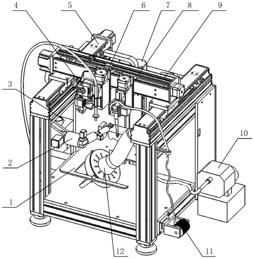
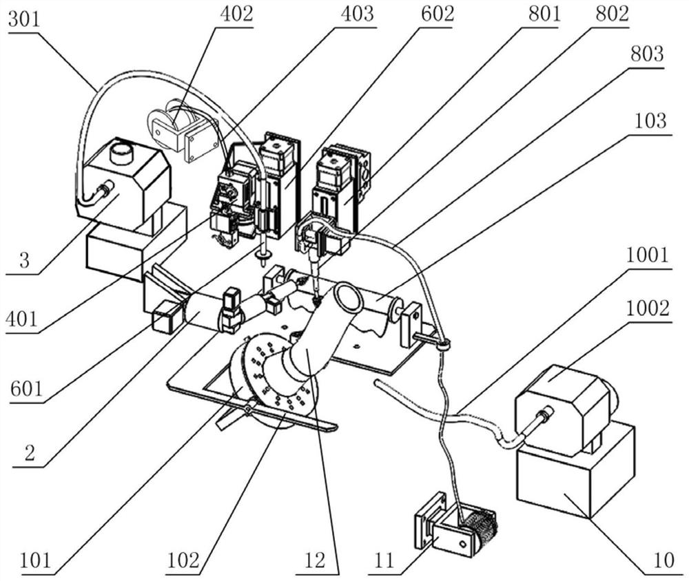
[0053] Such as Figure 1-9 As shown, the continuous fiber composite shell manufacturing equipment used in the continuous fiber composite shell manufacturing method of this embodiment includes: a loading platform 1, a six-degree-of-freedom manipulator 2, a vacuum pump 3, a thermoplastic material extrusion unit 4, and a Y-axis Movement unit 5 , vacuum auxiliary unit 6 , Z-axis movement unit 7 , wire winding mechanism 8 and X-axis movement unit 9 . The X-axis motion unit 9 and the Y-axis motion unit 5 form a translational motion unit, which is provided with two motion output ends, one of which is installed with a thermoplastic material extrusion unit 4 and a vacuum auxiliary unit 6 through a hanging plate 46, and the vacuum auxiliary unit 6 passes through an upgrade mechanism 602 Realize up and down movement; one installs the wire winding mechanism 8 through the lifting mechanism 801, and the wire winding mechanism 8 uses the wire feeding mechanism 802 to realize the function; th...


PUM


Abstract

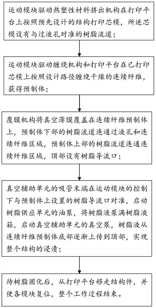
The invention discloses a method for manufacturing a continuous fiber composite material shell. The manufacturing process comprises the following steps: (1) driving a thermoplastic material extrusionmechanism to print a core mold on a printing platform according to a pre-designed structure by a motion module, wherein a resin runner aligned at a liquid through hole is formed in the core mold; (2)driving a winding mechanism and the printing platform to wind dried continuous fibers on the printed core mold according to a design path by the motion module so as to obtain a preform; (3) covering avacuum film on the continuous fiber preform by a laminating mechanism, wherein the resin runner in the lower part of the preform is communicated with the liquid through hole and the continuous fiberarea, the resin runner in the upper part of the preform is communicated with the continuous fiber area, and a resin orifice is formed in the top; (4) pumping the resin liquid tank with resin liquid, starting a vacuum pump of a vacuum auxiliary unit, and enabling the resin liquid to gradually transfer to the top from the bottom of the continuous fiber preform; (5) removing the structural componentfrom the printing platform after resin curing, and resetting each module. Therefore, the whole operating process is ended.

Description

technical field [0001] The invention relates to the technical field of continuous fiber composite material manufacturing, in particular to a method for manufacturing a continuous fiber composite material shell. Background technique [0002] As a strategic material for national development, carbon fiber has excellent characteristics such as high strength, high stiffness, low specific gravity, friction and wear resistance, and recyclable use. It is a new generation of high-performance and lightweight advanced materials. Composite materials made of it It has important application prospects in the fields of automobiles, ships, aerospace, rail transit, and medical equipment. However, traditional carbon fiber composite structural parts face the difficulties of complex manufacturing process, long production cycle, often requiring molds and difficult to realize complex structure manufacturing. For the manufacture of single-variety and small-batch structural parts, especially the ma...

Claims


Application Information

Patent Timeline
Patent Type & Authority Patents(China)
IPC IPC(8): B29C70/36
CPCB29C70/36
Inventor 栾丛丛傅建中姚鑫骅王振威刘加朋贺永
Owner ZHEJIANG UNIV
Learn More