
Formwork Erection Method and Formwork Structure of Column Beam and Frame Beam Joint

A formwork technology for frame beams and columns, which is applied in the fields of formwork/formwork/work frame, building structure, and on-site preparation of building components. Shorten the physical construction period, solve the problem of long production cycle and good demoulding effect

Active Publication Date: 2021-01-26
CHINA MCC5 GROUP CORP
View PDF4 Cites 0 Cited by
  • Summary
  • Abstract
  • Description
  • Claims
  • Application Information

AI Technical Summary

Problems solved by technology

[0003] The object of the present invention is to: aim at the above existing problems in the prior art, and invent a formwork erection method and formwork structure for the joints of cylindrical beams and frame beams, which can effectively solve the problem of low material utilization rate caused by the inability of a single shaped steel mold to be directly recycled The problem

Method used


Image

  • Formwork Erection Method and Formwork Structure of Column Beam and Frame Beam Joint
  • Formwork Erection Method and Formwork Structure of Column Beam and Frame Beam Joint
  • Formwork Erection Method and Formwork Structure of Column Beam and Frame Beam Joint

Examples


Embodiment 1

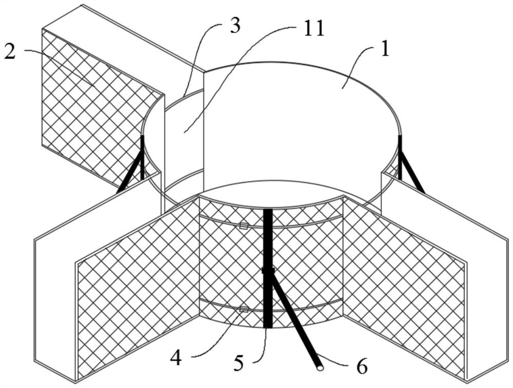
[0026] As shown in the figure, the formwork structure used for the joint construction of cylindrical beams and frame beams is made of wooden formwork. At the connection between the column and the frame beam, the circular column formwork 1 surrounds the formwork of the cylindrical steel bar grid, The frame beam formwork 2 is erected around the steel mesh of the frame beam, the arc-shaped column formwork 1 and the frame beam formwork 2 are connected at nodes, and the connection between the arc-shaped column formwork 1 and the frame beam formwork 2 is provided with a vertical opening 11.

[0027] At the junction of the arc-shaped column formwork 1 and the frame beam formwork 2, nails are nailed from the inside of the arc-shaped column formwork 1 to the end of the frame beam formwork 2 for connection.

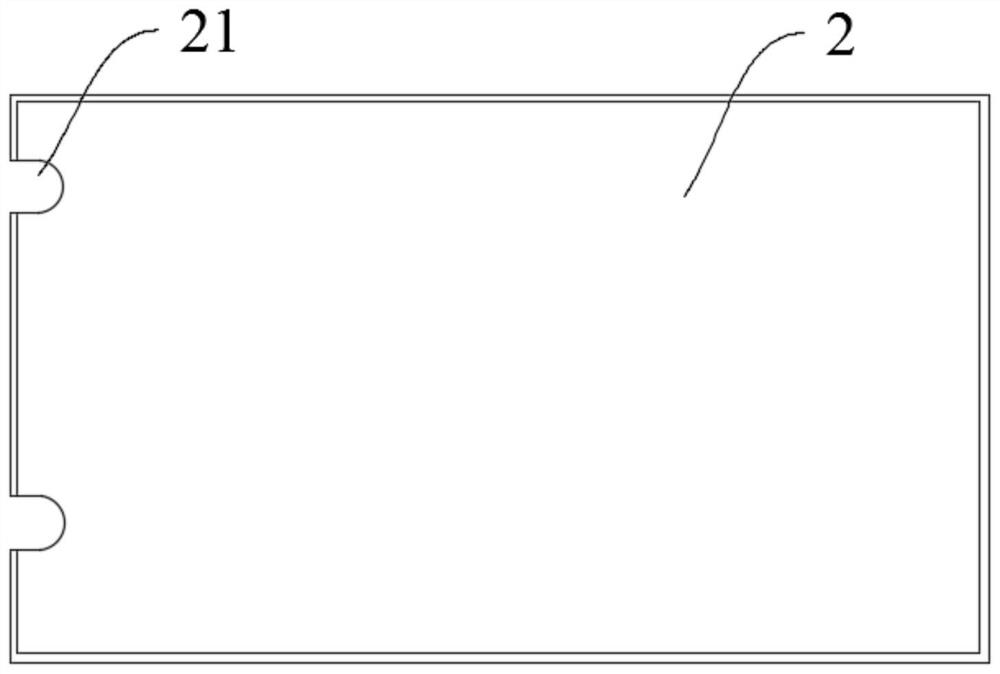
[0028] On the outside of the arc-shaped column formwork 1, several round steel rings 3 for fastening are provided at vertical intervals. An end notch 21 is provided at the joint b...

Embodiment 2

[0037] The formwork erection method of the above-mentioned cylindrical beam and frame beam joint, the method comprises the following steps:

[0038]S1: Production of arc-shaped column formwork: 5mm wooden formwork is used as raw material. If there are several connection points between the column and the frame beam, the arc-shaped column formwork of the corresponding number of sections is cut out. Before cutting, each section of arc-shaped column formwork is accurately measured. According to the radius of the cylinder, the woodworking machinery is used for simple bending processing;

[0039] S2: Installation of arc-shaped column formwork: first install the arc-shaped column formwork around the steel mesh of the cylinder, and use the round steel ring to hoop the arc-shaped column formwork from the outside. Multiple round steel rings can be set, and the vertical spacing is 60cm , to achieve sufficient fixation strength;

[0040] S3: Installation of the frame beam formwork: the f...


PUM


Abstract

The invention discloses a formwork erection method for cylindrical beam and frame beam nodes and a formwork structure. The formwork structure is made of a wooden formwork, arc-shaped column formworksare erected around a cylindrical steel bar net and frame beam formworks are erected around a steel bar net of frame beams at the connecting positions of cylinders and the frame beams, so that the arc-shaped column formworks and the frame beam formworks are connected at the nodes, and the portions, connected with the frame beam formworks, of the arc-shaped column formworks are provided with vertical openings. Compared with the prior art, by adopting the wooden formwork erection method for cylindrical beam and frame beam nodes, the problem of long production period of forming steel molds can besolved, and thus an entity construction period is shortened; the formwork structure is light in weight, the formwork erection and removal speed is high, and a demolding effect is good. The high cost for producing forming steel molds with single nodes can be saved; the wooden formwork can be also repeatedly utilized through simple finishing after use, and the problem is solved that a single formingsteel mold cannot be directly recycled and accordingly the material utilization rate is low.

Description

technical field [0001] The invention belongs to the technical field of building construction, and in particular relates to a formwork erection method and formwork structure for a column beam and a frame beam joint. Background technique [0002] Conventional cylindrical beam and frame beam joint formwork generally adopts shaped steel formwork, which needs to be customized and produced in advance according to the structural size. The use of shaped steel formwork for construction requires drawing, blanking, welding, and customized production in advance according to the size of each node, and the production cycle is long; the quality of a single formwork is large, and often installation and disassembly need to be assisted by tower cranes or small lifting machinery. , the construction speed is slow; because the formwork of a single node cannot be turned over, its cost is all spent on one node, resulting in high cost and low formwork utilization. In the case of various nodes, it ...

Claims


Application Information

Patent Timeline
Patent Type & Authority Patents(China)
IPC IPC(8): E04G13/00
CPCE04G13/00
Inventor 阳刚胥海波王文斌
Owner CHINA MCC5 GROUP CORP
Learn More