Radial flow type rotating mechanical impeller

A rotary machine, radial flow technology, applied in mechanical equipment, non-variable-capacity pumps, engine components, etc., can solve the problem of high power loss, and achieve the effect of reducing the axial force on the back, enhancing acceleration, and balancing the axial force

Inactive Publication Date: 2018-12-25
NO 719 RES INST CHINA SHIPBUILDING IND
View PDF5 Cites 2 Cited by
  • Summary
  • Abstract
  • Description
  • Claims
  • Application Information

AI Technical Summary

Problems solved by technology

[0006] The technical problem to be solved by the present invention is the problem of high power loss in the axial force balance structure of the existing radial flow rotating machinery impeller

Method used


Image

  • Radial flow type rotating mechanical impeller
  • Radial flow type rotating mechanical impeller
  • Radial flow type rotating mechanical impeller

Examples


Embodiment Construction

[0020] The invention provides a radial-flow type rotary mechanical impeller, which can realize. The present invention will be described in detail below in conjunction with the accompanying drawings and specific embodiments.

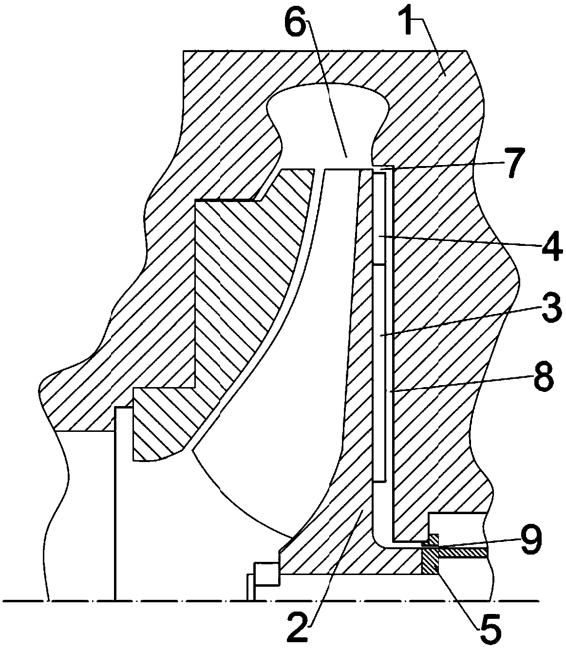
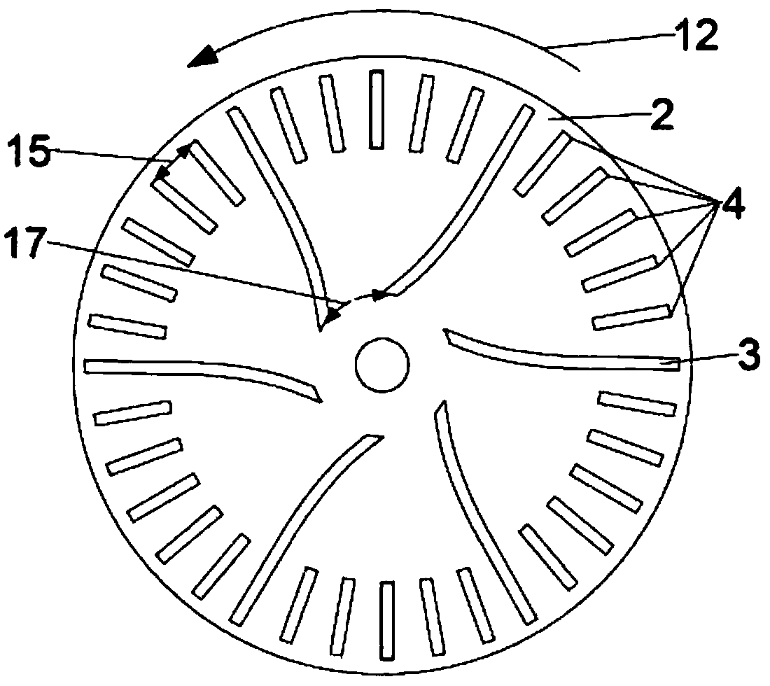
[0021] Such as image 3 As shown, the radial-flow rotary mechanical impeller provided by the present invention includes the impeller main body, including main blades 3 and edge blades 4 . There are a plurality of main blades 3, which are evenly distributed on the back of the impeller body along the circumferential direction of the impeller body, and the main blades 3 are protrudingly arranged. There are a plurality of edge blades 4, which are evenly arranged between the inlet sections of adjacent main blades 3 along the circumferential direction, and the edge blades 4 protrude. There is a small axial gap between the main blade 3 and the edge blade 4 and the fixed wall surface on the back side of the impeller.

[0022] In the present invention, main bla...


PUM


Abstract

The invention discloses a radial flow type rotating mechanical impeller. The radial flow type rotating mechanical impeller comprises an impeller body, and a plurality of main blades and a plurality ofedge blades are arranged on the back surface of the impeller body. The main blades are uniformly distributed on the back surface of the impeller body in the peripheral direction of the impeller body,and the main blades are arranged in a protruding mode. The edge blades are uniformly arranged between the inlet sections of the adjacent main blades in the peripheral direction, and the edge blades are arranged in a protruding mode. According to the radial flow type rotating mechanical impeller, the blade consistency in an area with a larger radius on the back portion of the impeller body is significantly increased, meanwhile, the increase of the blade consistency of an area with a smaller radius is avoided, so that the circumferential velocity increases rapidly after leakage fluid enters a back clearance of the impeller body, the circumferential velocity of the leakage fluid further increases with the decrease of the radius under the drive of the blades on the back portion of the impeller body, the pressure is reduced at the same time, the reduction of fluid pressure in the area with the larger radius facilitates the reduction of the axial force on the back portion of the impeller body, and the axial force of the impeller body is balanced.

Description

technical field [0001] The invention relates to the technical field of radial-flow rotary mechanical impellers, in particular to a radial-flow rotary mechanical impeller. Background technique [0002] Due to its compact size and excellent variable working conditions, radial-flow rotating machinery is widely used in various fields of national production, such as centrifugal pumps in the petrochemical industry, turbochargers in the automotive industry, centrifugal compressors and centripetal turbines in the aviation industry, etc. During its operation, the axial thrust of the fluid on the back of the impeller is usually greater than that on the front of the impeller. When the operating pressure of the rotating machine is high, the impeller bears a large axial force directed to the front of the impeller, which may exceed the bearing capacity of the thrust bearing. Design some special structures such as balance holes, back vanes, etc. to balance the axial force. [0003] The im...

Claims


Application Information

Patent Timeline
Patent Type & Authority Applications(China)
IPC IPC(8): F04D29/22F04D29/28F01D5/04
CPCF01D5/048F04D29/2216F04D29/28
Inventor 马灿王苇苟金澜赵振兴代路吴君柯志武
Owner NO 719 RES INST CHINA SHIPBUILDING IND
Why Eureka
Try Eureka