Vibration isolation device of power mechanism and electric vehicle including vibration isolation device

A technology for electric vehicles and power mechanisms, applied in power devices, electric power devices, transportation and packaging, etc., to achieve the effects of reducing radiation noise, not being easily damaged, and solving vibration durability

Pending Publication Date: 2018-12-25
NIO CO LTD
View PDF0 Cites 0 Cited by
  • Summary
  • Abstract
  • Description
  • Claims
  • Application Information

AI Technical Summary

Problems solved by technology

[0004] The technical problem to be solved by the present invention is to provide a vibration isolation device for a power mechanism and an electric vehicle including the vibration isolation device, aiming at isolating the vibration transmitted from the power mechanism to the controller, reducing the vibration received by the internal components of the controller, and prolonging the life of the controller. The service life of the controller is used to solve the technical problems of radiation noise and vibration durability of the controller

Method used


Image

  • Vibration isolation device of power mechanism and electric vehicle including vibration isolation device
  • Vibration isolation device of power mechanism and electric vehicle including vibration isolation device
  • Vibration isolation device of power mechanism and electric vehicle including vibration isolation device

Examples


Embodiment 1

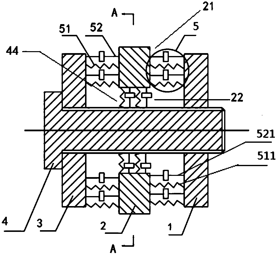
[0041] The casing 3 of the electric power mechanism, the casing 2 of the controller and the limit locking block 1 are arranged along the axial direction of the through bolt 4, and are respectively passed through by the through bolt 4. There is an axial gap 21 between them; a vibration isolation structure 5 is provided in the axial gap 21 to connect the adjacent two. Preferably, a plurality of the vibration isolation structures 5 are arranged in the axial gap 21 and arranged around the circumference of the through bolt 4 .

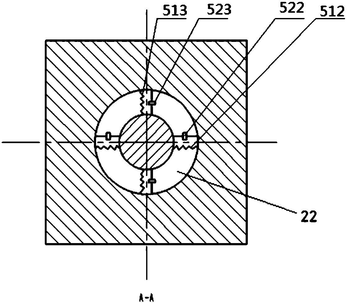
[0042] The housing 2 of the controller has a through hole 41 through which the through-hole bolt 4 passes, and there is a circumferential gap 22 between the through-hole 41 and the through-bolt 4 , and a vibration isolation structure 5 is arranged in the circumferential gap 22 , to connect the housing 2 of the controller with the through bolt 4.

[0043] Preferably, a plurality of vibration isolation structures 5 are arranged in the circumferential gap 22 ...

Embodiment 2

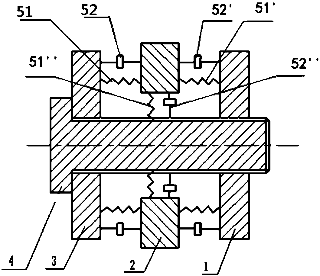
[0045] Please refer to the attached image 3As shown, the top of the middle bolt 4 is fixedly connected to the housing 3 of the electric power mechanism through threaded connection, welding, riveting and other structures, and the bottom end of the middle bolt 4 is connected to the limit locking block through threads, welding, riveting and other structures. 1 fixed connection. One set of elastic structures 51 and one set of damping structures 52 are respectively connected to the casing 3 of the electric power mechanism, and the other end is connected to the first side of the casing 2 of the controller; another set of elastic structures 51' and another One end of the set of damping structures 52' is respectively connected to the second side of the controller housing 2, and the other end is connected to the limit locking block 1; one end of another set of elastic structures 51" and another set of damping structures 52" are respectively connected to The third side of the housing ...

Embodiment 3

[0047] In addition to the same connection as the above-mentioned group of elastic structures 51 and a group of damping structures 52 in the second embodiment, a group of elastic structures 51 and a group of damping structures 52 are also arranged in the Z direction, which are respectively connected to the gear box and the middle bolt. 4. The casing of the controller and the limit locking block 1 are elastically connected to form a vibration-isolation connection in X, Y, and Z directions.


PUM


Abstract

The invention relates to a vibration isolation device of a power mechanism of an electric vehicle and the electric vehicle including the vibration isolation device. One end of the vibration isolationdevice is connected to an electric power mechanism, and the other end of the vibration isolation device is connected to a controller. The vibration isolation device mainly comprises a vibration isolation structure, and the vibration isolation structure includes one or more sets of elastic structures and one or more sets of damping structures. The vibration isolation device reduces vibration transmitted by the power mechanism to a shell of the controller in different directions by multi-directional vibration isolation, reduces the vibration to internal components of the controller, prolongs theservice life, reduces radiation noise of the shell of the controller, and improves the riding comfort of the electric vehicle, thereby enhancing the user experience.

Description

technical field [0001] The invention relates to the technical field of vibration control, in particular to a vibration isolation device for a power mechanism and an electric vehicle including the vibration isolation device. Background technique [0002] In recent years, with the gradual popularization of electric vehicles, users' demands on the vibration and noise comfort (NVH), ease of maintenance, and durability of vehicles are increasing. However, in the current electric drive system of electric vehicles, due to the requirements of space layout and electromagnetic compatibility (EMC), the power mechanism and the controller are arranged in a close connection, which results in the transmission of vibration generated by the power mechanism. To the controller, it will cause many problems. [0003] For example, the motor, gearbox and inverter (PEU) in the power mechanism are closely connected. The original rigid connection method will cause the vibration generated by the moto...

Claims


Application Information

Patent Timeline
Patent Type & Authority Applications(China)
IPC IPC(8): F16F15/04F16F15/08F16F15/023F16F15/02
CPCB60K1/00F16F15/02F16F15/023F16F15/04F16F15/08
Inventor 肖宁
Owner NIO CO LTD
Why Eureka
Try Eureka