An electromagnetic heat storage combustion purification system for treating organic waste gas

A heat storage combustion and organic waste gas technology, applied in the direction of combustion type, combustion method, incinerator, etc., can solve the problems of low catalytic combustion, poor heat storage effect, etc., to increase gas temperature, improve exhaust gas purification effect, and improve efficiency Effect

Active Publication Date: 2019-11-29
安徽尘缘节能环保科技有限公司
View PDF5 Cites 0 Cited by
  • Summary
  • Abstract
  • Description
  • Claims
  • Application Information

AI Technical Summary

Problems solved by technology

[0004] The purpose of the present invention is to provide an electromagnetic heat storage combustion purification system for treating organic waste gas, by setting a heat conduction column on the heat exchanger, and the heat conduction column is located in the heat storage box, and at the same time, a heat absorbing rod is arranged at the position of the combustion box The heat in the combustion box is absorbed by the heat conduction plate and discharged into the water in the heat storage box through the heat conduction rod. The gas in the heat conduction box is preheated by the heat conduction of the hot water in the heat storage box, which solves the problem of the existing combustion purification system. The heat storage effect is not good, which leads to the problem that the catalytic combustion is too low

Method used


Image

  • An electromagnetic heat storage combustion purification system for treating organic waste gas
  • An electromagnetic heat storage combustion purification system for treating organic waste gas
  • An electromagnetic heat storage combustion purification system for treating organic waste gas

Examples


Embodiment Construction

[0036] The following will clearly and completely describe the technical solutions in the embodiments of the present invention with reference to the accompanying drawings in the embodiments of the present invention. Obviously, the described embodiments are only some, not all, embodiments of the present invention. Based on the embodiments of the present invention, all other embodiments obtained by persons of ordinary skill in the art without creative efforts fall within the protection scope of the present invention.

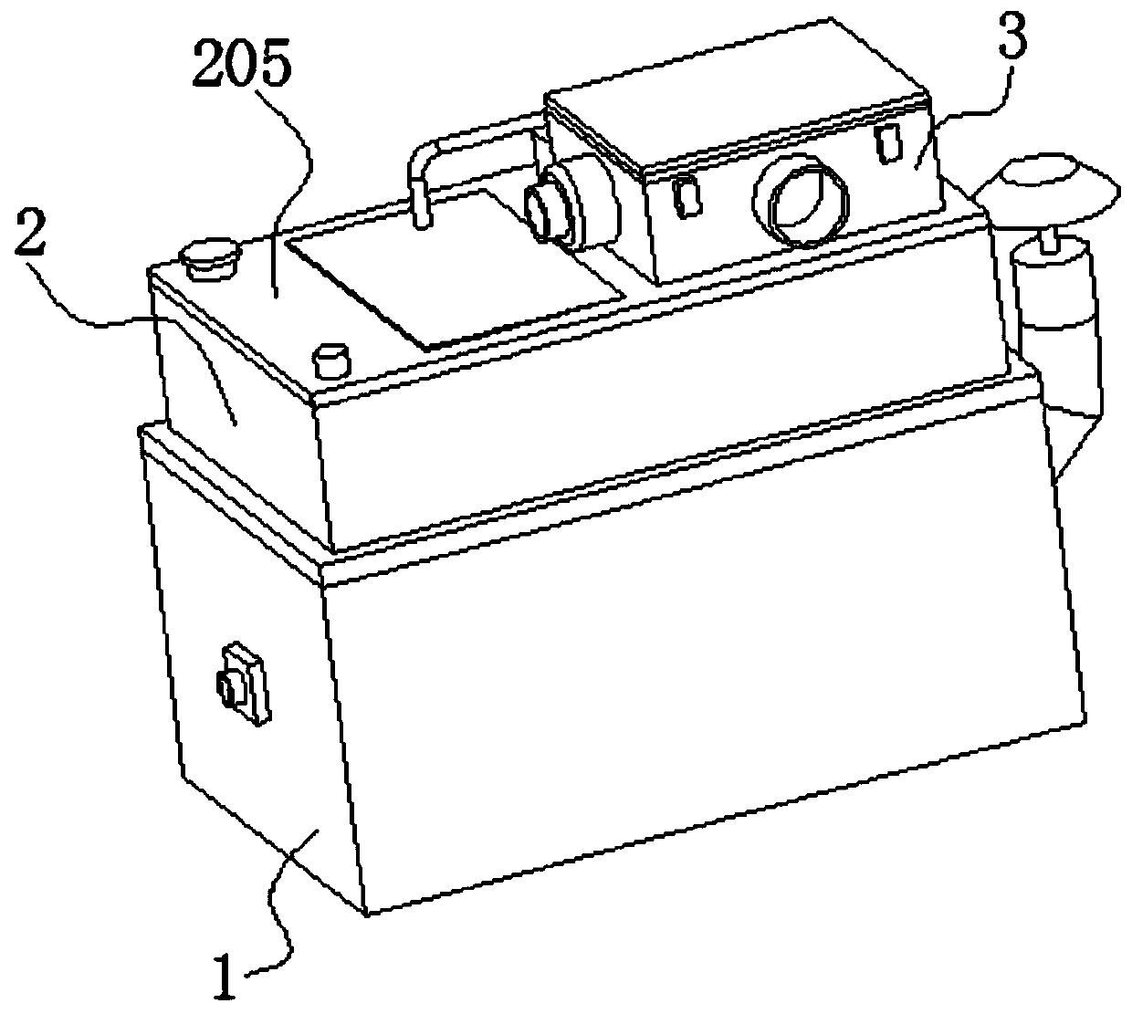
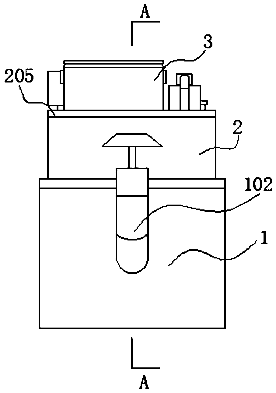
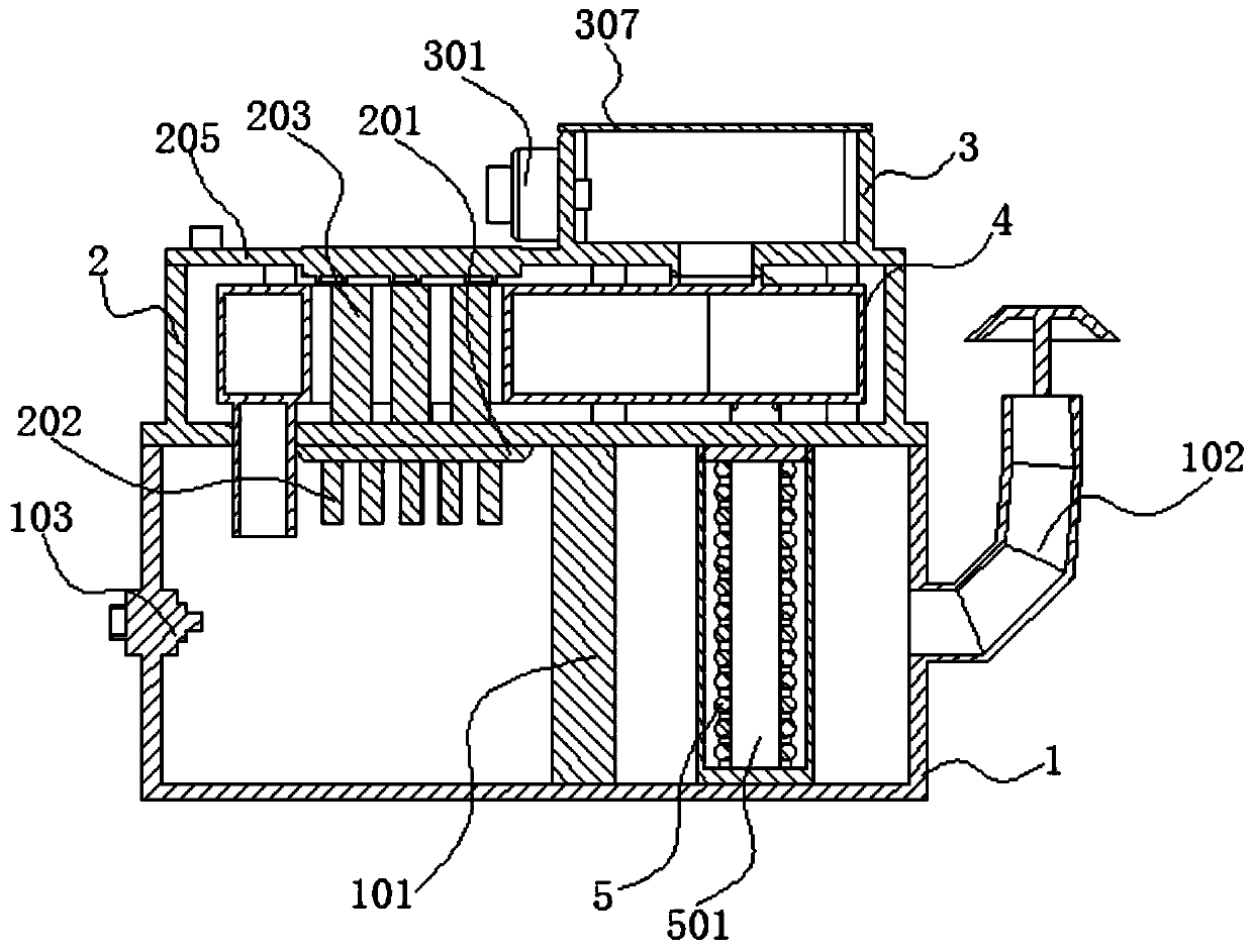
[0037] see Figure 1-11 As shown, the present invention is an electromagnetic heat storage combustion purification system for treating organic waste gas, comprising a combustion box 1, a heat storage box 2 is fixed on the top of the combustion box 1, a treatment box 3 is fixed on the top of the heat storage box 2, and the heat storage A heat conduction box 4 is fixed inside the box 2;

[0038] The top surface of the combustion box 1 is fixedly connected with the b...


PUM


Abstract

The invention discloses an electromagnetic heat storage combustion purification system for treating organic waste gas, and relates to the technical field of exhaust gas treatment. The electromagneticheat storage combustion purification system comprises a combustion box, a heat storage box is fixedly arranged at the top of the combustion box, a processing box is fixedly arranged at the top of theheat storage box, and a heat conduction box is fixedly arranged in the heat storage box. The top surface of the combustion box is fixedly connected with the bottom surface of the heat storage box, thecombustion box is internally and fixedly provided with a heat exchanger, the heat exchanger is used for absorbing heat generated by combustion gas in the combustion box, and a group of heat conduction columns is fixedly arranged in the heat exchanger. The electromagnetic heat storage combustion purification system is provided with the heat conducting columns on the heat exchanger, the heat conduction columns are located in the heat storage box, and at the same time, a heat absorbing rod and a heat conducting plate are arranged at the position of the combustion box to absorb the heat in the combustion box and discharge the heat to water in the heat storage box through the heat conducting rod, the gas in the heat conducting box is preheated by the heat conduction of the hot water in the heat storage box, and the problem that an existing combustion purification system has low catalytic combustion due to poor heat storage effect is solved.

Description

technical field [0001] The invention belongs to the technical field of waste gas treatment, and in particular relates to an electromagnetic heat storage combustion purification system for treating organic waste gas. Background technique [0002] Waste gas treatment is also known as waste gas purification. Waste gas treatment refers to the pretreatment of waste gas generated in industrial sites and factory workshops before being discharged to the outside, so as to meet the national waste gas discharge standards. General waste gas treatment includes organic waste gas treatment, dust Waste gas treatment, acid-base waste gas treatment, odor waste gas treatment and air sterilization, disinfection and purification, etc. [0003] Traditional exhaust gas treatment uses catalytic combustion to purify the air. However, the existing catalytic combustion device discharges the exhaust gas into the heat exchanger for heating and then discharges it to the vicinity of the combustion head of...

Claims


Application Information

Patent Timeline
Patent Type & Authority Patents(China)
IPC IPC(8): F23G7/06F23L15/00
CPCF23G7/068F23L15/00Y02E20/34
Inventor 姜化朋
Owner 安徽尘缘节能环保科技有限公司
Why Eureka
Try Eureka