
WLAN ranging technology based on software radio platform

A technology of software radio and platform, which is applied in the direction of radio wave measurement system, measurement device, and utilization of re-radiation, etc. It can solve problems such as unaligned phases, unfriendly users, and large environmental impact

Active Publication Date: 2018-12-25
CHONGQING UNIV OF POSTS & TELECOMM
View PDF7 Cites 7 Cited by
  • Summary
  • Abstract
  • Description
  • Claims
  • Application Information

AI Technical Summary

Problems solved by technology

The traditional ranging technology is mainly based on RSSI or fingerprints. Such methods are greatly affected by the environment and require a large cost to build a database. Therefore, indoor measurement based on CSI (Channel State Information) Distance technology has gradually become the mainstream distance measurement technology
[0003] At present, there are mainly the following mainstream CSI-based indoor ranging technologies. The first one is to use CSI amplitude and establish a propagation model for ranging. Compared with RSSI, this method has finer-grained channel information, so Higher precision distance information can be obtained, but this type of method also has the disadvantage of being greatly affected by the environment
The second is a ranging technology based on the angle of arrival AoA (Arrival of Angle), which requires the use of multiple antennas, using the phase difference of multiple antennas to estimate the angle, and then establish a geometric model for distance estimation, but This technology needs to combine multiple stations to perform ranging, and it cannot be used in many systems with only a single node
This method is firstly affected by errors, and slight phase errors will cause the phases to be out of alignment, resulting in a large deviation in the settlement of the real phase, and this method of using two-way communication also needs to run the program at the receiving end. When the sender sends the program package, it needs to return the data package immediately, which is very unfriendly to the user

Method used


Image

  • WLAN ranging technology based on software radio platform
  • WLAN ranging technology based on software radio platform
  • WLAN ranging technology based on software radio platform

Examples


Embodiment Construction

[0033] specific implementation plan

[0034] Further describe the technical scheme of the present invention in detail below in conjunction with accompanying drawing:

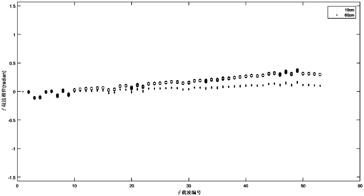
[0035] use as figure 1 The receiver signal processing block diagram design flow diagram shown in the test, specifically includes the following steps:

[0036] Step 1, according to figure 1 The flow diagram of the signal processing flow design receiver shown in the figure ensures that the obtained CSI is the data obtained from a single run without interference from previous data;

[0037] Step 2. Design the flow diagram of the transmitter according to the standard IEEE 802.11n protocol transmitter signal processing flow, so that the signal-related parameters of the transmitter are consistent with those of the receiver;

[0038] Step 3. Start the transmitter and receiver to obtain the original CSI phase φ i,k ,It can be expressed as

[0039] φ i,k = θ i,k -k(λ pdd +λ sfo )+β i

[0040] where k is the subc...


PUM


Abstract

The invention discloses a WLAN ranging technology based on a software radio platform. Firstly, a GPS atomic clock with high precision is obtained by a GPS disciplined oscillator ( GPSDO ) to be used as a reference clock source of the software radio platform, and the phase error caused by sampling frequency offset is eliminated by the method. Then the phase error caused by carrier frequency offsetis eliminated by subtracting the phase value of a first subcarrier used for communication from all subcarriers. Then the phase error caused by packet detection delay is eliminated by setting the sampling time in advance to zero. Finally, cubic spline interpolation is used for eliminating the ambiguity of whole circles among sub-carriers, and equipment is corrected once by a known distance to obtain the phase difference between the initial sub-carriers, while the actual measured distance can be obtained by adding the known distance to the actual measured distance difference, and higher rangingaccuracy can be obtained by the method.

Description

technical field [0001] The invention belongs to indoor positioning technology, and specifically relates to a method for measuring distance by acquiring WLAN channel state information at a receiving end and using the phase of the WLAN channel state information under a software radio platform. Background technique [0002] In recent years, the rapid development of the Internet and the Internet of Things has increased people's demand for location-based services (LBS), such as quickly searching for parking spaces in underground parking lots, and finding elevator entrances in large shopping malls. The GPS (Global Positioning System) based on satellite positioning cannot locate indoors, and indoor positioning technology has become one of the technologies most closely related to people's production and life. As one of the most important parts of indoor positioning, distance measurement directly determines the accuracy of positioning. Improving the accuracy of indoor distance measur...

Claims


Application Information

Patent Timeline
Patent Type & Authority Applications(China)
IPC IPC(8): G01S11/02
CPCG01S11/02
Inventor 田增山康庆飞何维周牧谢良波杨小龙胡安琪任梦恬
Owner CHONGQING UNIV OF POSTS & TELECOMM
Learn More