U-core single-phase permanent magnet synchronous motor driven miniature centrifugal pump

A synchronous motor, single-phase permanent magnet technology, used in synchronous motors with static armatures and rotating magnets, machines/engines, magnetic circuit rotating parts, etc., can solve the difficulty of accurate experimental verification and modification design of U-shaped motors Difficulties, inconvenient use and installation, etc.

Pending Publication Date: 2018-12-25
JIANGMEN TIANDE ELECTRICAL APPLIANCE CO LTD
View PDF4 Cites 0 Cited by
  • Summary
  • Abstract
  • Description
  • Claims
  • Application Information

AI Technical Summary

Problems solved by technology

[0002] Miniature centrifugal pumps are widely used in a large number of areas. In view of the fact that traditional miniature centrifugal pumps are driven by asynchronous motors and have low efficiency, a large number of existing technologies have been directly driven by U-shaped motors in the past 10 years, which significantly saves energy and materials. However, its U-shaped structure The asymmetric shape whose bottom edge is located on the side of the pump axis and whose radial distance is too large often makes the use and installation of the pump inconvenient, while the electromagnetic design of the motor involves complex calculations involving dozens of mutually constrained input variables. The U-shaped motor is due to the structure It is novel, special and too small to be verified accurately by experiments. So far, no electromagnetic calculation formula program and special computer design software have been established, so it is very difficult to modify the design

Method used


Image

  • U-core single-phase permanent magnet synchronous motor driven miniature centrifugal pump
  • U-core single-phase permanent magnet synchronous motor driven miniature centrifugal pump
  • U-core single-phase permanent magnet synchronous motor driven miniature centrifugal pump

Examples


Embodiment Construction

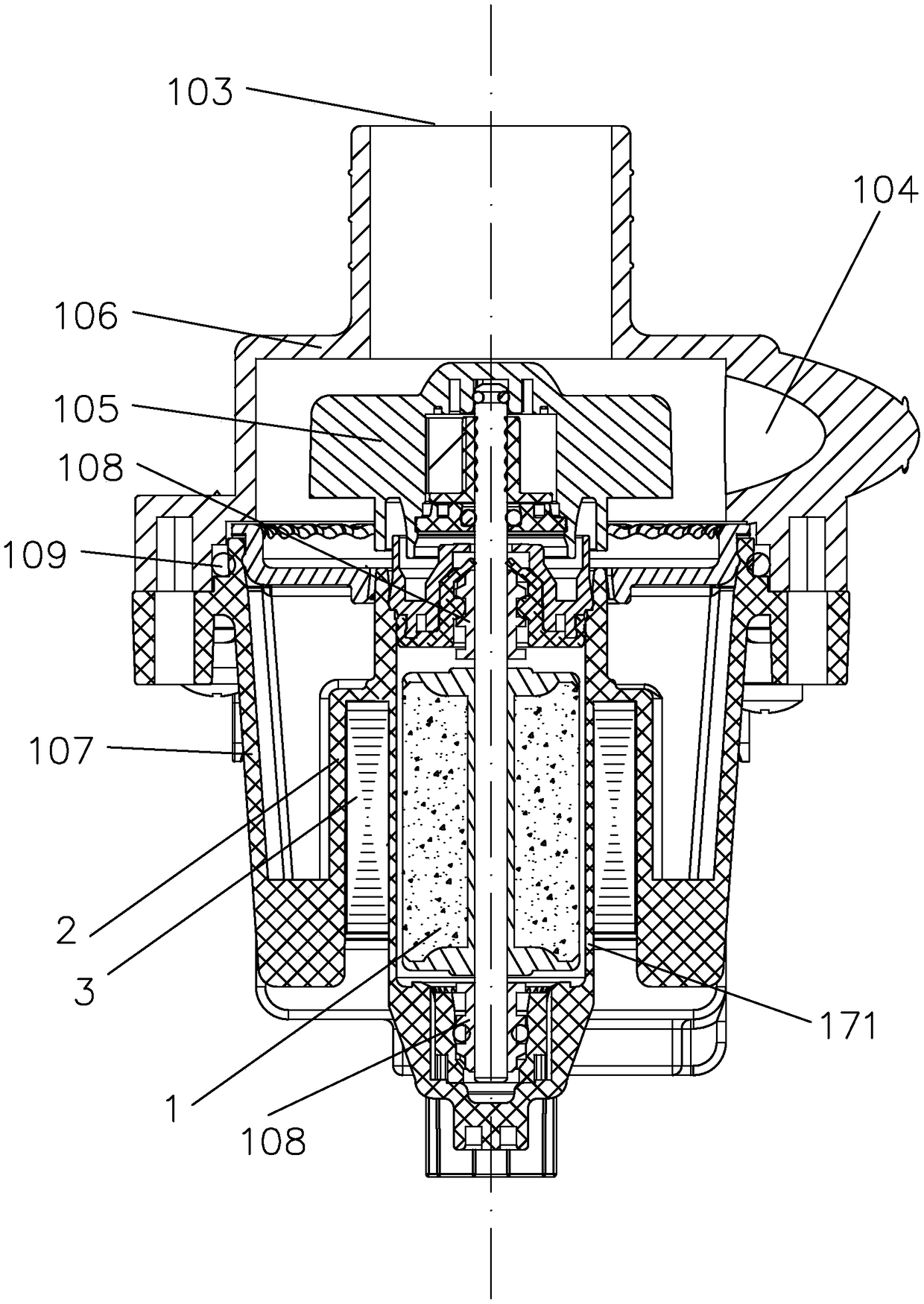
[0020] The centrifugal pump in the embodiment of the present invention is improved on the basis of the original drainage pump for household appliances, and it inherits the basic structure of the centrifugal pump as follows: figure 1 with figure 2 shown, including:

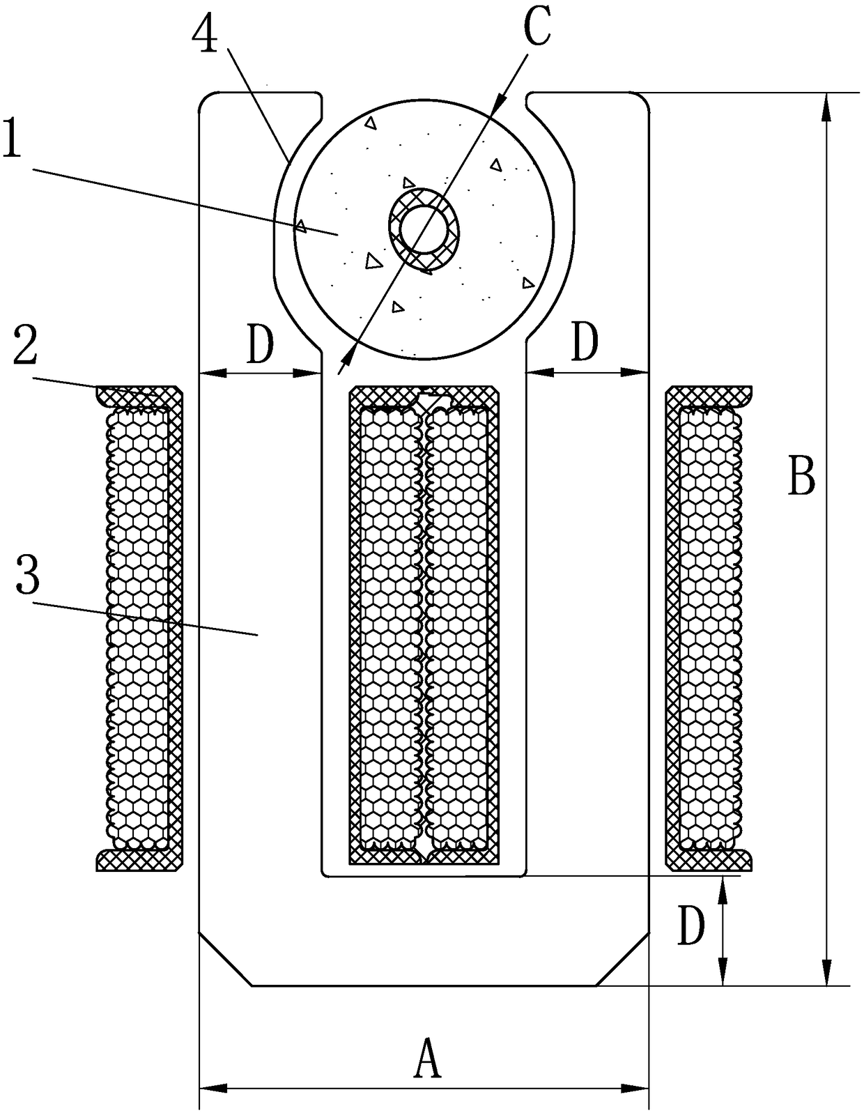
[0021] - U-shaped motor ( figure 1 It shows its permanent magnet rotor 1, stator winding 2 and laminated iron core 3) and its centrifugal impeller 105 coaxially driven by a starting mechanism. Centrifugal impeller 105 is injection molded and has 4 radial blades (the number of blades can also be 3, 5 or 6, using an odd number of blades is more conducive to reducing vibration and noise). According to the requirements of water pressure, the diameter is 30-40mm. Flow requirements, the blade width is 8 ~ 15mm.

[0022] ——The pump cover 106 that surrounds the impeller and acts as a volute, which has an axial suction port 103 and a tangential discharge port 104; of course, it can also be designed as a radial discharge...


PUM


Abstract

A micro centrifugal pump driven by a U-shaped iron core single-phase permanent magnet synchronous motor, comprises a pump cover having an axial inlet and a radial or tangential outlet, a centrifugal impeller and a U-shaped iron core single-phase permanent magnet synchronous motor coaxially driving the impeller; the impeller has a diameter of 20 to 70mm in ; The motor comprises a permanent magnet rotor which is a cylindrical shape magnetized by two radial poles and has a diameter of 10-40mm; a stator comprising a U-shaped laminated iron core and a stator winding through which the iron core passes; The upper part of the U-shaped two arms is formed to abut on the left and right pole boots of the cylindrical surface of the permanent magnet rotor; The ratio (A/C) of the width (A) of the U-shaped outer edge to the diameter (C) of the permanent magnet rotor is not less than 1.75. The design can shorten the radial dimension of the pump, which is advantageous to the installation and use of thepump, and the comprehensive cost of the electromagnetic material is reduced, so that the performance-price ratio is better.

Description

technical field [0001] The invention relates to a miniature centrifugal pump driven by a U-shaped iron core single-phase permanent magnet synchronous motor (abbreviated as "U-shaped motor"), especially relates to the coordination of its mechanical and electromagnetic structures; the IPC classification can belong to F04D25 / 06. Background technique [0002] Miniature centrifugal pumps are widely used in a large number of areas. In view of the fact that traditional miniature centrifugal pumps are driven by asynchronous motors and have low efficiency, a large number of existing technologies have been directly driven by U-shaped motors in the past 10 years, which significantly saves energy and materials. However, its U-shaped structure The asymmetric shape whose bottom edge is located on the side of the pump axis and whose radial distance is too large often makes the use and installation of the pump inconvenient, while the electromagnetic design of the motor involves complex calcu...

Claims


Application Information

Patent Timeline
Patent Type & Authority Applications(China)
IPC IPC(8): H02K21/14H02K1/27H02K1/12F04D13/06F04D25/06
CPCH02K1/12H02K1/2706H02K21/14F04D13/0606F04D25/0606H02K2213/03
Inventor 区长钊邓海锋林华波王红标
Owner JIANGMEN TIANDE ELECTRICAL APPLIANCE CO LTD
Why Eureka
Try Eureka