
Laser welding method and laser welding apparatus

A technology of laser welding and laser beam, which is applied in the direction of laser welding equipment, welding equipment, conductors, etc., can solve the problems of decreased welding strength and increased resistance, achieve a good welding state, and prevent the formation of air holes

Active Publication Date: 2018-12-28
TOYOTA JIDOSHA KK
View PDF4 Cites 2 Cited by
  • Summary
  • Abstract
  • Description
  • Claims
  • Application Information

AI Technical Summary

Problems solved by technology

When fragments of multiple metal oxide films exist at the metal interface of the welded portion or when pores remain at the metal interface, problems such as decreased welding strength and increased electrical resistance may occur

Method used

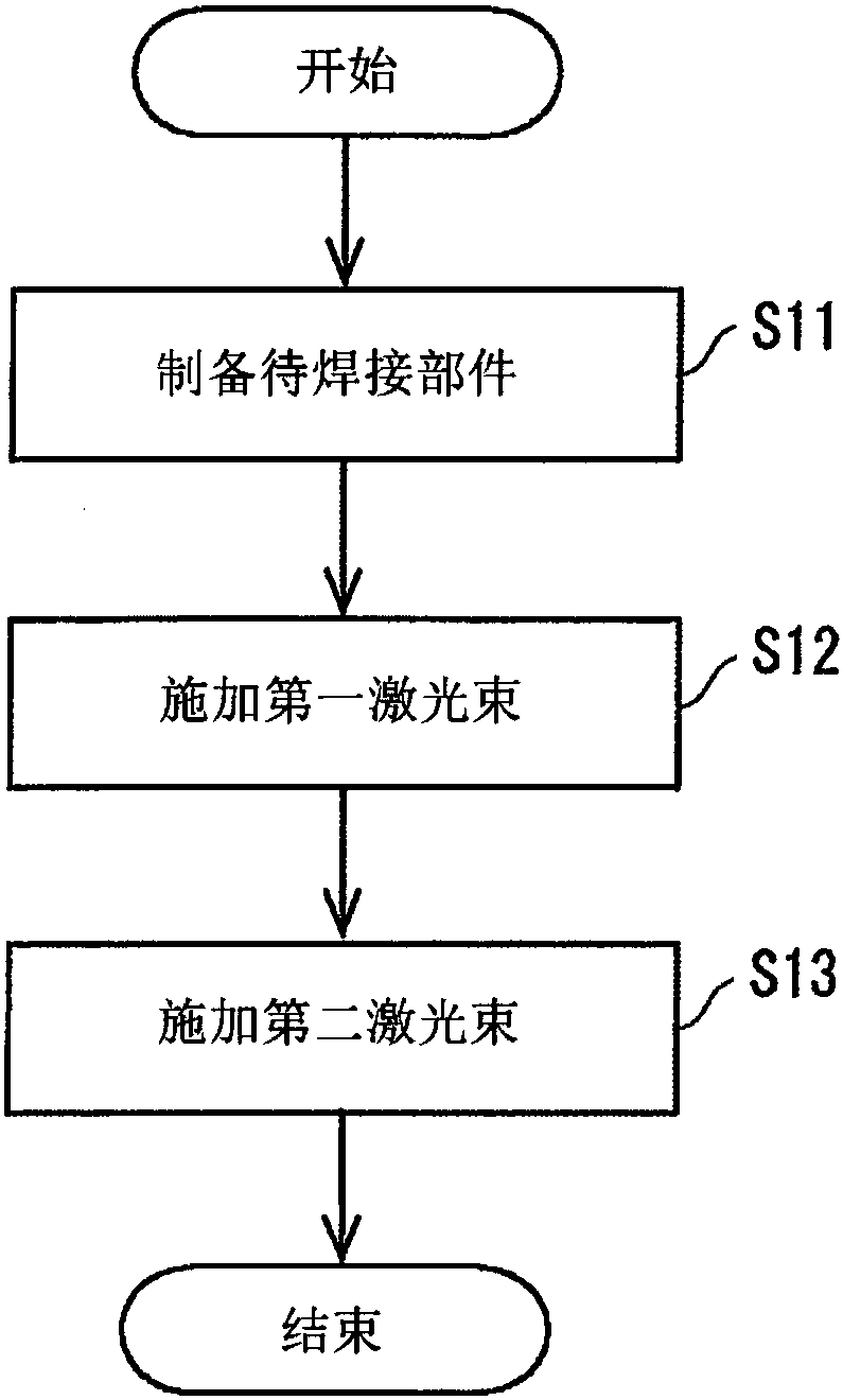
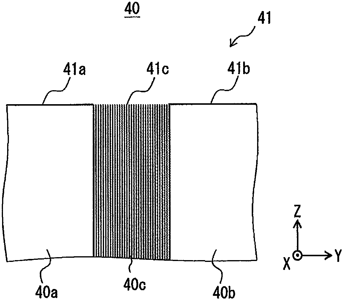

Image

  • Laser welding method and laser welding apparatus
  • Laser welding method and laser welding apparatus
  • Laser welding method and laser welding apparatus

Examples


Embodiment approach

[0030] A laser welding method and a laser welding device according to the embodiments will be described below. First, a laser welding device according to this embodiment will be described. After that, the laser welding method will be explained.

[0031] (laser welding device)

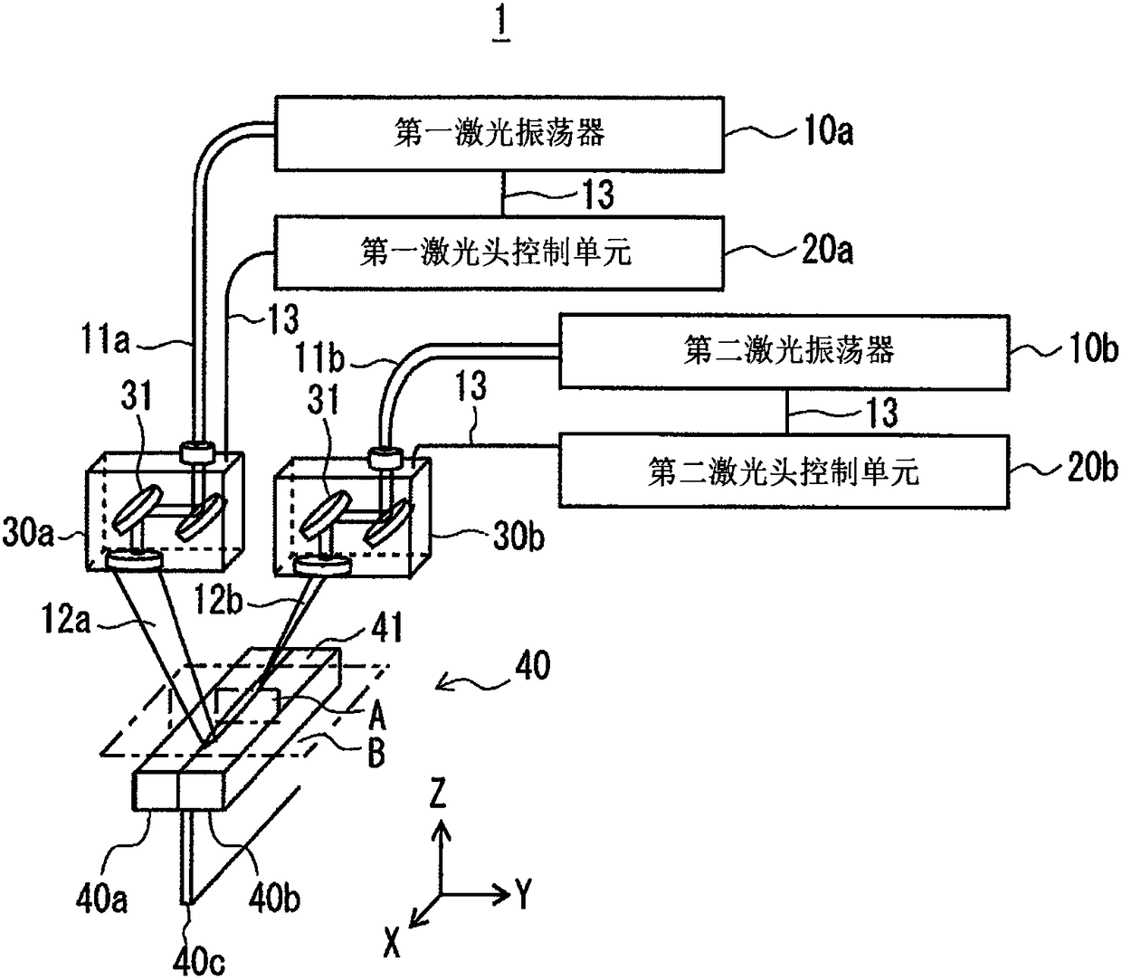
[0032] First, the configuration of the laser welding device will be described. figure 1 is a configuration diagram showing an example of the configuration of the laser welding device according to the embodiment.

[0033] Such as figure 1 As shown, the laser welding device 1 includes a first laser oscillator 10a, a second laser oscillator 10b, a first laser head control unit 20a, a second laser head control unit 20b, a first welding head 30a and a second welding head 30b. The first laser oscillator 10a is connected to the first welding head 30a through an optical cable 11a. The second laser oscillator 10b is connected to the second welding head 30b through an optical cable 11b. The first laser osci...


PUM


Abstract

A laser welding method and a laser welding apparatus capable of preventing formation of blowholes and obtaining an excellent welled state are provided. An embodiment is a laser welding method for a component to be welded 40 including a third metal component 40c sandwiched between first and second metal components 40a and 40b, in which the metal components are welded to each other by scanning a laser beam in a first direction perpendicular to a direction in which the third metal component 40c is sandwiched, in which a welded part 42 is formed by applying a first laser beam 12a while scanning itin the first direction and thereby melting and then solidifying the component to be welded 40.

Description

technical field [0001] The present disclosure relates to a laser welding method and a laser welding device. For example, the present disclosure relates to a foil laminate in which the foil laminate is sandwiched between two plate terminals and the foil laminate and the plate terminal are welded together on the end faces of the clamped foil laminate. Laser welding method and laser welding device. Background technique [0002] Japanese Unexamined Patent Application Publication No. 2015-217422 (hereinafter referred to as Patent Document 1) discloses a laser welding method for welding in an integrated manner by using a laser beam including sandwiching an upper charge collecting plate and The part to be soldered is the laminated foil between the lower charge collecting plates. In the laser welding method disclosed in Patent Document 1, a first laser beam with relatively low power is applied from above the upper charge collecting plate. In addition, the second laser beam and th...

Claims


Application Information

Patent Timeline
Patent Type & Authority Applications(China)
IPC IPC(8): B23K26/067B23K26/21
CPCB23K26/067B23K26/21B23K26/0608B23K26/24B23K26/082B23K26/064B23K2101/38B23K26/211B23K26/704
Inventor 立山望美小林裕臣大桥文德柴田义范
Owner TOYOTA JIDOSHA KK
Learn More