Indoor positioning and tracking system based on grating matrix technology

An indoor positioning and tracking system technology, which is applied to the exploration of optical devices, the use of optical devices, and image data processing. , the effect of reducing network bandwidth

Inactive Publication Date: 2018-12-28
昆明简酷科技有限公司
View PDF5 Cites 8 Cited by
  • Summary
  • Abstract
  • Description
  • Claims
  • Application Information

AI Technical Summary

Problems solved by technology

[0004] 2. Artificial intelligence visual recognition technology needs to upload the moving image data of indoor people or objects collected by each camera in real time to the background for recognition and analysis, and the more cameras and the more people or objects entering the room, the generated The amount of data will increase sharply; a large amount of data transmission and computing requirements will lead to a substantial increase in investment in network bandwidth and background server configuration, which will eventually lead to a substantial increase in background hardware costs and operation and maintenance costs;
[0005] 3. For artificial intelligence visual recognition technology, when the appearance characteristics of people or objects change (such as deliberate camouflage, occlusion behavior, etc.), it will be difficult to carry out continuous automatic tracking, which will lead to problems such as misjudgment or data loss;
[0006] 4. Artificial intelligence visual recognition technology needs to record, compare, judge and track the characteristic data of people or objects in real time. Due to the huge amount of data, the calculation and analysis time is long, and it is difficult for the equipment with general configuration to achieve instant result data return. , it is difficult to ensure the timeliness of the application

Method used


Image

  • Indoor positioning and tracking system based on grating matrix technology
  • Indoor positioning and tracking system based on grating matrix technology
  • Indoor positioning and tracking system based on grating matrix technology

Examples


Embodiment 1

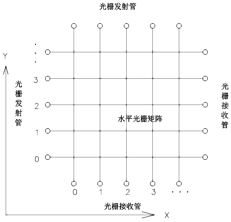
[0030] Embodiment one: see attached Figure 1-2 , using a grating matrix arrangement in the horizontal direction. Install the grating shooting device (grating emitting tube and grating receiving tube) at the same height (20-120cm above the ground) on the side walls around the room. If there is an object blocking the wall, install the grating device on the object On the outside, ensure that the grating device is not blocked. The two opposite side walls are respectively equipped with a grating emitting tube and a grating receiving tube. ...or the distance between the grating receiving tubes 1 and 2, 2 and 3...) does not exceed 15cm, and the grating adopts an infrared grating with good anti-interference; the indoor horizontal direction is precisely divided into coordinates, when people or objects enter When indoors, the moving process will interfere with the grating in the horizontal x and y coordinate directions, and the interference data set of the x and y coordinate position ...

Embodiment 2

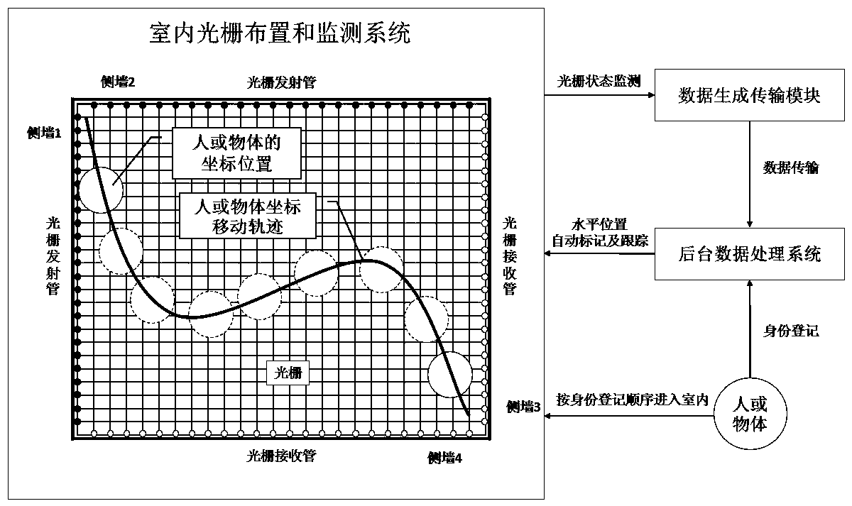
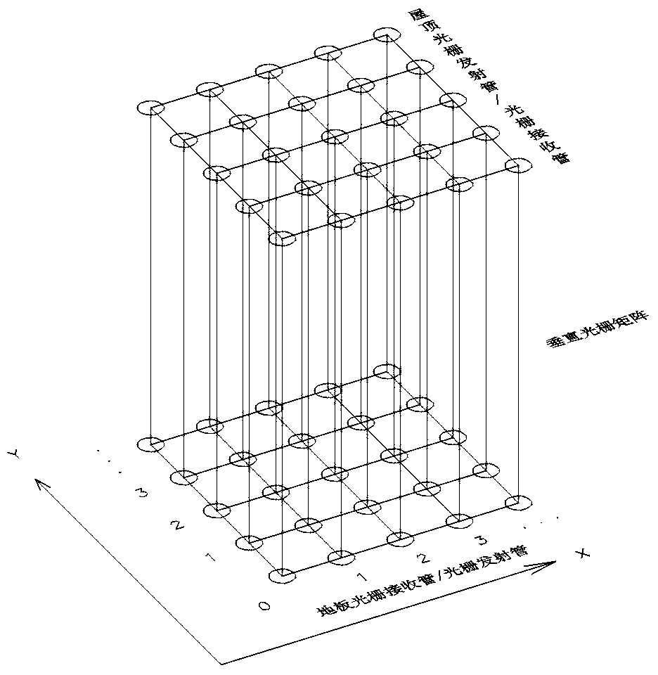
[0031] Embodiment two: with reference to attached Figure 3-4 , a grating matrix arrangement in the vertical direction is adopted, and the grating adopts an infrared grating with better anti-interference. The floor and roof of the indoor space are embedded with grating shooting devices. The grating transmitting tube and the grating receiving tube are respectively installed on the indoor roof and floor. The distance between each pair of gratings is less than or equal to 15cm. The grating shooting device is networked, and Connect the data generation and transmission module of grating signal monitoring, and transmit the grating detection data to the background data processing system in real time. The background system automatically marks and connects the coordinate position of the continuous movement of the person or object according to the coordinate position arranged by the grating matrix, so as to obtain the coordinate position of the person or object Real-time moving track. ...

Embodiment 3

[0032] Embodiment three: see attached Figure 5-6 , a grating matrix arrangement in the vertical direction is adopted, and the grating adopts an infrared grating with better anti-interference. The grating ranging devices are installed in a matrix on the underside of the indoor roof. Each ranging device includes a miniature grating transmitting tube and a miniature grating receiving tube. The interval between the grating ranging devices can be adjusted according to different position accuracy requirements. Generally, the aisle spacing is set between 8-15cm, and the spacing between places that need to accurately monitor the actions of people or objects is 5-8cm. According to the indoor space coordinate planning, the grating ranging device is networked and connected to the data generation transmission module, and the measurement data of the grating ranging device is transmitted to the background data processing system in real time. The background system marks the incoming data ac...


PUM


Abstract

The invention discloses an indoor positioning and tracking system based on grating matrix technology, comprising an indoor grating arrangement and a monitoring system. The indoor grating arrangement refers to a grating matrix system arranged horizontally or vertically in a room. The monitoring system comprises a data generating transmitting module and a background data processing system. The datagenerating transmitting module is integrated with the grating receiving tube, and transmits the state information data of the grating receiving tube to the background data processing system in real time. The background data processing system automatically marks and connects the coordinate positions of the continuously moving persons or objects according to the related information to obtain a real-time moving track of persons or objects, and performs the identification confirmation with the identity registration condition of persons or objects entering the room. According to the indoor positioning and tracking system based on grating matrix technology, the grating matrix of the system is simple to construct, small in investment, accurate in positioning and good in popularization prospect.

Description

technical field [0001] The invention relates to an indoor positioning and track tracking system, in particular to an indoor precise positioning and track tracking system based on grating matrix technology. Background technique [0002] For people or objects without special tracking equipment (GPS, RFID, etc.), indoor positioning and tracking of movement trajectories are performed only based on the shape of the person or object itself. At present, artificial intelligence visual recognition technology is mainly used. Such as face recognition) or object appearance features, etc., for image analysis and mobile location recording, this method has the following shortcomings or deficiencies: [0003] 1. Artificial intelligence visual recognition technology relies on the recognition and judgment of certain unique identification features of people or objects (such as human faces, appearance packaging, etc.). Therefore, it is necessary to deploy a lot of cameras in different positions...

Claims


Application Information

Patent Timeline
Patent Type & Authority Applications(China)
IPC IPC(8): G01B11/00G01V8/20G06T7/246
CPCG01B11/002G01V8/20G06T7/246
Inventor 吴学雷
Owner 昆明简酷科技有限公司
Why Eureka
Try Eureka