
Self-resetting concrete-filled circular steel tube frame beam-column joint with energy dissipation parts on webs

A technology of beam-column joints and concrete columns, which is applied in the direction of building components, earthquake resistance, building types, etc., can solve the problems of inner partitions, difficult replacement of energy-consuming parts, and damage to floors, etc., to achieve uniform force distribution and reduce labor costs , to achieve the effect of assembly

Active Publication Date: 2019-01-01
XI'AN UNIVERSITY OF ARCHITECTURE AND TECHNOLOGY +1
View PDF9 Cites 8 Cited by
  • Summary
  • Abstract
  • Description
  • Claims
  • Application Information

AI Technical Summary

Problems solved by technology

[0004] Aiming at the deficiencies in the prior art, the purpose of the present invention is to provide a self-resetting circular steel tube concrete frame beam-column joint with energy-dissipating parts in the web, so as to adapt to the circular steel tube concrete frame widely used in building structures and solve the existing problems. The beam-column joints of the circular steel pipe concrete frame do not have the self-resetting function, the earthquake damage is difficult to repair, the on-site welding workload is large, the internal partition affects the quality of concrete pouring, the energy-consuming parts are not easy to replace, and the deformation of the energy-consuming parts damages the floor.

Method used


Image

  • Self-resetting concrete-filled circular steel tube frame beam-column joint with energy dissipation parts on webs
  • Self-resetting concrete-filled circular steel tube frame beam-column joint with energy dissipation parts on webs
  • Self-resetting concrete-filled circular steel tube frame beam-column joint with energy dissipation parts on webs

Examples


Embodiment Construction

[0033] Specific embodiments of the present invention are provided below, and it should be noted that the present invention is not limited to the following specific examples, and all equivalent transformations done on the basis of the technical solutions of the present application all fall within the protection scope of the present invention.

[0034] In the present invention, unless stated to the contrary, the used orientation words such as "upper and lower" generally refer to definitions based on the drawings of the corresponding drawings.

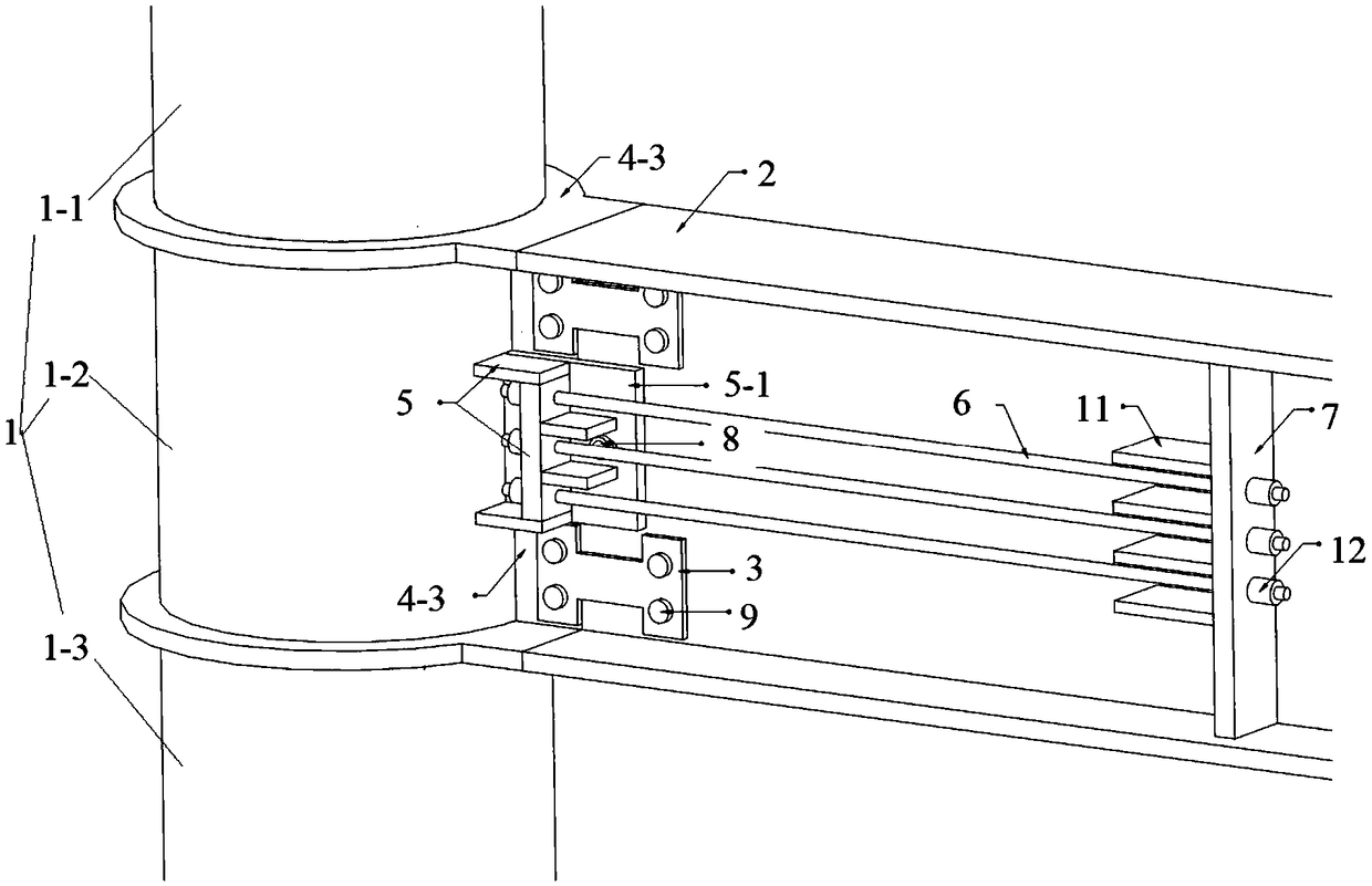
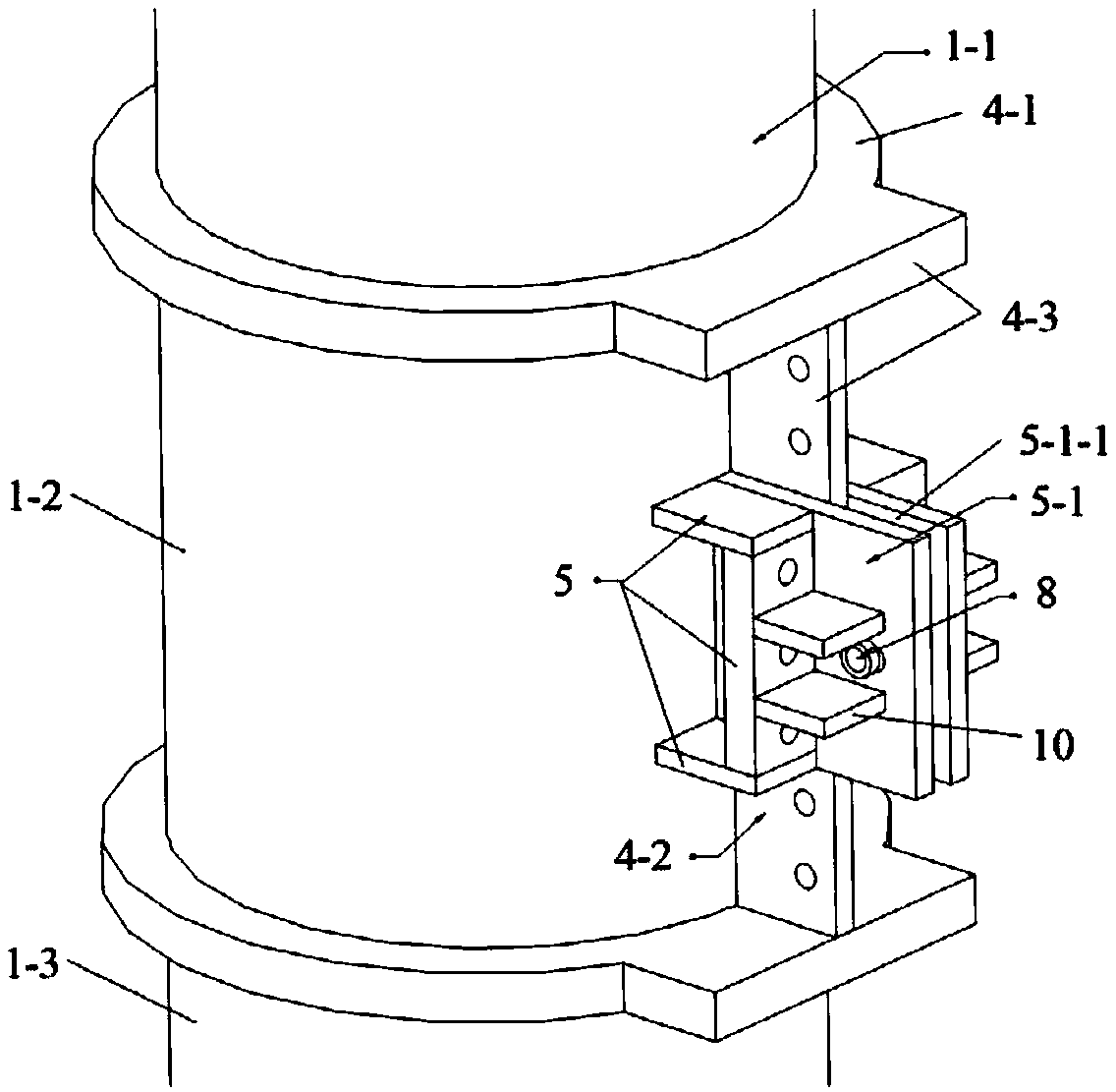
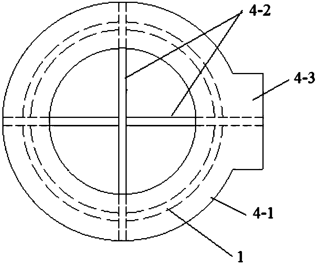
[0035] Such as figure 1 As shown, the present invention discloses a self-resetting circular steel pipe concrete frame beam-column node with energy-dissipating parts on the web, including a circular steel pipe concrete column 1, an H-shaped steel beam 2, an energy-dissipating part 3, a column connector 4, Groove connector 5, prestressed steel strand 6 and anchor plate 7; column connector 4 includes annular plate 4-1 and column through plat...


PUM


Abstract

The invention discloses a self-resetting concrete-filled circular steel tube frame beam-column joint with energy dissipation parts on webs. The self-resetting concrete-filled circular steel tube framebeam-column joint comprises a concrete-filled circular steel tube column, an H-shaped steel beam, the energy dissipation parts, column connectors, grooved connectors, prestressed steel strands and ananchoring plate, wherein one end of each prestressed steel strand is anchored to the bottom of the corresponding grooved connector and the other end of each prestressed steel strand is anchored to the anchoring plate; and two ends of each energy dissipation part are connected to the corresponding web of an H-shaped short beam and the corresponding web of the H-shaped steel beam. Energy dissipation plates are arranged on the webs, so that the self-resetting concrete-filled circular steel tube frame beam-column joint has no influence on the construction of floors and is capable of being easilyreplaced after seismic damage and avoiding the situation that the energy dissipation plates are deformed resulting in cracking of the floors. Various processes such as welding of the column part and the grooved connectors of the self-resetting concrete-filled circular steel tube frame beam-column joint are completed in a factory, and then transported to a site for direct assembly after being prefabricated in the factory so as to realize prefabrication, reduce the labor cost and reduce the risk of overhead working.

Description

technical field [0001] The invention belongs to the technical field of earthquake prevention and disaster reduction of building structures, and in particular relates to a self-resetting circular steel pipe concrete frame beam-column node with webs and energy-dissipating parts. Background technique [0002] The self-resetting structure has the advantages of dissipating seismic energy and reducing seismic action, reducing or avoiding damage to the main structure and minimizing residual deformation of the structure. Afterwards, only the energy-consuming parts need to be replaced, and the structure can be quickly restored to normal working condition, which can significantly reduce the post-earthquake repair cost. It meets the needs of national economic development and the owner's requirements for the seismic performance of the structure. In recent years, the research on self-resetting structures has attracted extensive attention of researchers. [0003] Because the confinement...

Claims


Application Information

Patent Timeline
IPC IPC(8): E04B1/58E04B1/30E04B1/98E04H9/02
CPCE04B1/30E04B1/58E04H9/021E04H9/025
Inventor 王先铁何罗谢川东冯云堂罗遥丁艳刘成
Owner XI'AN UNIVERSITY OF ARCHITECTURE AND TECHNOLOGY
Learn More