Air-source water heater and defrosting method thereof

An air source water heater and compressed air technology, applied in fluid heaters, lighting and heating equipment, damage protection, etc., can solve problems such as inability to guarantee hot water supply, low and incomplete defrosting efficiency, and improve defrosting efficiency , high defrosting efficiency, and the effect of reducing energy waste

Pending Publication Date: 2019-01-01
ZHEJIANG AMA & HIEN TECH
View PDF1 Cites 2 Cited by
  • Summary
  • Abstract
  • Description
  • Claims
  • Application Information

AI Technical Summary

Problems solved by technology

[0005] Therefore, the technical problem to be solved by the present invention is to overcome the defects that the air source water heater in the prior art cannot guarantee hot water supply when defrosting, and the defrosting efficiency is low and incomplete, thereby providing an air source water heater and its defrosting method, defrosting does not hinder the air source water heater from making hot water, and the defrosting time is short, the efficiency is high, and the energy utilization rate is high

Method used


Image

  • Air-source water heater and defrosting method thereof
  • Air-source water heater and defrosting method thereof

Examples


Embodiment 1

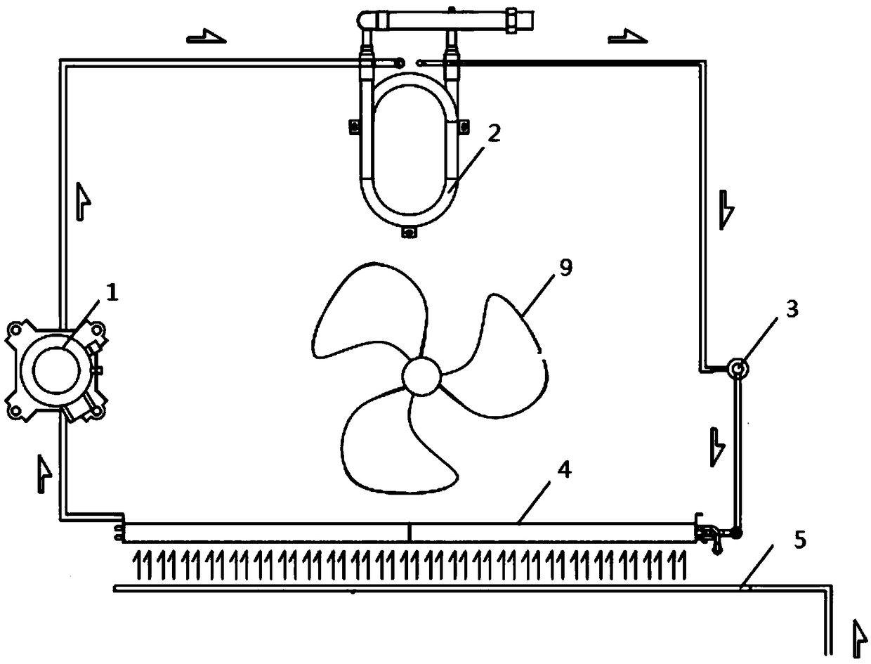
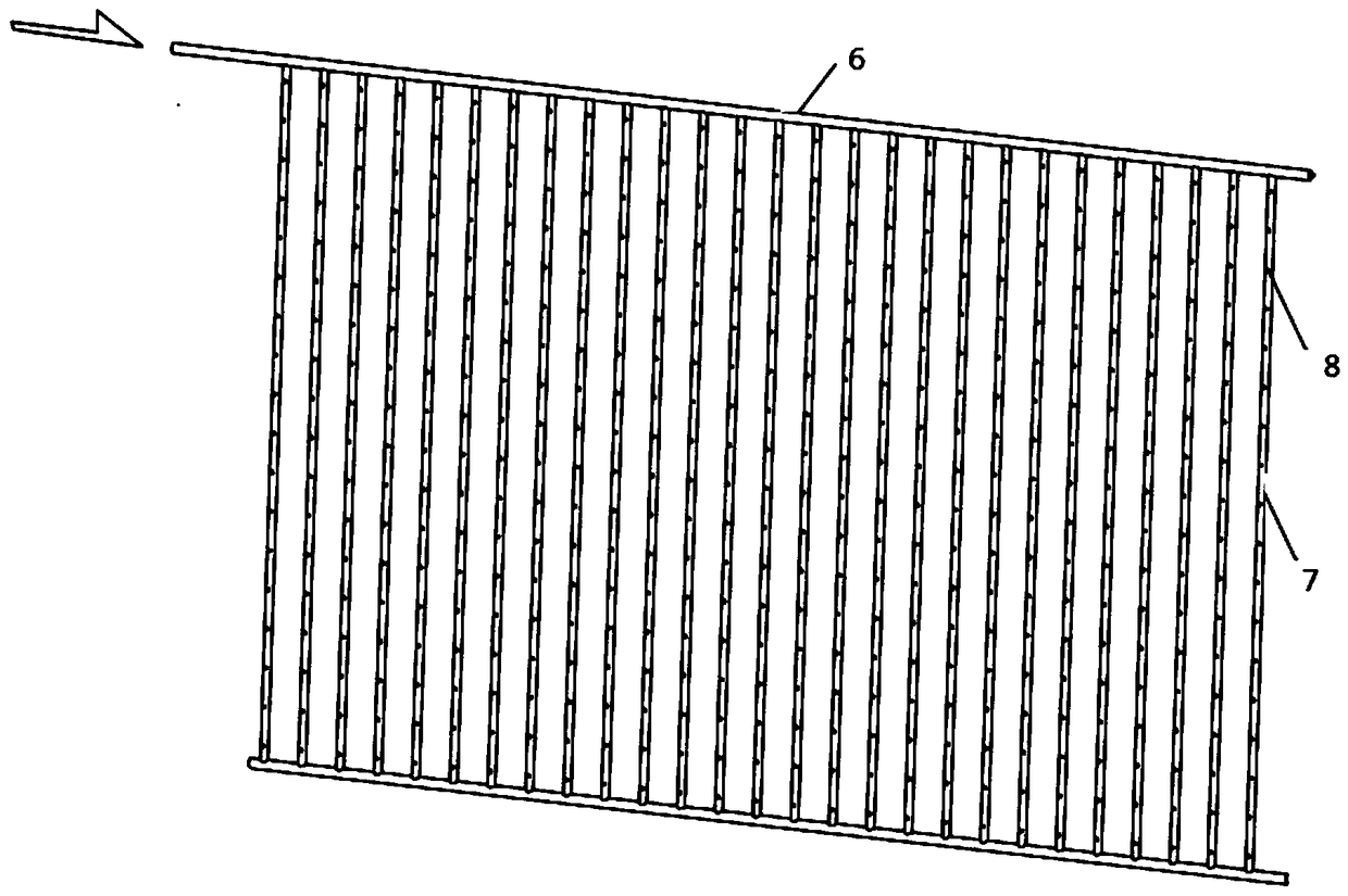
[0032] Such as figure 1 and 2 A specific implementation of the air source water heater shown includes: a compression cycle pipeline, including a compressor 1, a condenser 2, a throttle valve 3 and an evaporator 4 connected in sequence, and the outlet of the evaporator 4 is connected to the The inlet of the compressor 1; the defrosting device, which is arranged on one side of the evaporator 4, is stored inside for blowing air to the surface of the evaporator 4, so as to provide the defrosting of the surface of the evaporator 4. Compressed air for heat and power. Among them, the compressor 1 converts the low-temperature and low-pressure refrigerant gas absorbed from the evaporator 4 into a high-temperature and high-pressure refrigerant gas by doing work, thereby obtaining energy for exchanging heat with the equipment in the compression cycle line; the condenser 2 Used for heat exchange between the high-temperature and high-pressure refrigerant gas flowing out of the compressor...

specific Embodiment approach

[0041] A specific embodiment of a defrosting method for an air source water heater, comprising:

[0042] S1: monitoring the first temperature outside the compression cycle pipeline and the second temperature inside the evaporator 4 in real time;

[0043] S2: When the first temperature is less than the first preset value and the second temperature is less than the second preset value, compare the difference between the first temperature and the second temperature with the third preset value, and when When the difference is greater than the third preset value, and the interval time reaches the first predetermined time, the defrosting device is controlled to open, and the surface of the evaporator 4 is blown and defrosted until the second temperature When the fourth preset value is reached or the blowing and defrosting time reaches the second predetermined time, the blowing and defrosting is stopped, wherein the fourth preset value is greater than the second preset value; as long...


PUM


Abstract

The invention relates to the technical field of water heaters, in particular to an air-source water heater. The air-source water heater comprises a compression circulating pipeline and a defrosting device; the compression circulating pipeline comprises a compressor, a condenser, a throttling valve and an evaporator which are connected sequentially; an outlet of the evaporator is connected with aninlet of the compressor; the defrosting device is arranged on one side of the evaporator; and compressed air for blowing the surface of the evaporator to provide heat and power which are required during defrosting of the surface of the evaporator is stored inside the defrosting device. The invention further provides a defrosting method of the air-source water heater. Production of hot water by theaid of the air-source water heater is not hindered while defrosting is performed, the defrosting time is short, the efficiency is high, and the energy utilization rate is high.

Description

technical field [0001] The invention relates to the technical field of water heaters, in particular to an air source water heater and a defrosting method thereof. Background technique [0002] The air source water heater absorbs the low-temperature heat in the air, vaporizes it through the fluorine medium, and then compresses it through the compressor to increase the temperature, and then converts it through the heat exchanger to heat the water. The high-temperature heat energy after compression is used to heat the water temperature. The air source water heater overcomes the shortcomings of solar water heaters relying on sunlight for heating and inconvenient installation. Since the work of the air source water heater is to exchange heat through the medium, it does not require direct contact between the electric heating element and the water, avoiding the danger of electric water heater leakage, and also preventing the danger of explosion and poisoning of the gas water heater...

Claims


Application Information

Patent Timeline
Patent Type & Authority Applications(China)
IPC IPC(8): F24H4/02F25B47/02
CPCF24H4/02F25B47/02
Inventor 黄元躬
Owner ZHEJIANG AMA & HIEN TECH
Why Eureka
Try Eureka