
Optical fiber temperature sensor based on surface plasmon resonance and strain compensation

A surface plasmon and strain compensation technology, applied to thermometers, thermometers, instruments, etc. that change physically/chemically, can solve problems such as deviation of temperature measurement results, influence on resonance wavelength, and inability to eliminate the influence of strain, making it less susceptible and less prone to Effects of Electromagnetic Interference

Pending Publication Date: 2019-01-01
辽宁省计量科学研究院
View PDF0 Cites 2 Cited by
  • Summary
  • Abstract
  • Description
  • Claims
  • Application Information

AI Technical Summary

Problems solved by technology

Since the geometric size and structure of photonic crystal fiber and metal also affect the resonance wavelength, when the fiber sensor is affected by stress and strains, it will cause deviations in the temperature measurement results
However, the current fiber optic sensor based on surface plasmon resonance technology cannot eliminate the influence of strain on the measurement results.

Method used


Image

  • Optical fiber temperature sensor based on surface plasmon resonance and strain compensation
  • Optical fiber temperature sensor based on surface plasmon resonance and strain compensation
  • Optical fiber temperature sensor based on surface plasmon resonance and strain compensation

Examples


Embodiment Construction

[0023] In order to make the object, technical solution and advantages of the present invention clearer, the specific structure, principle and working process of the present invention will be further described in detail below in conjunction with specific embodiments and with reference to the accompanying drawings.

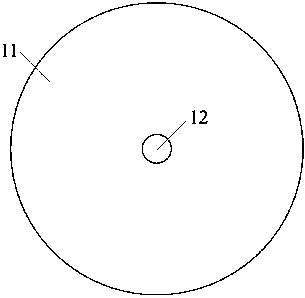
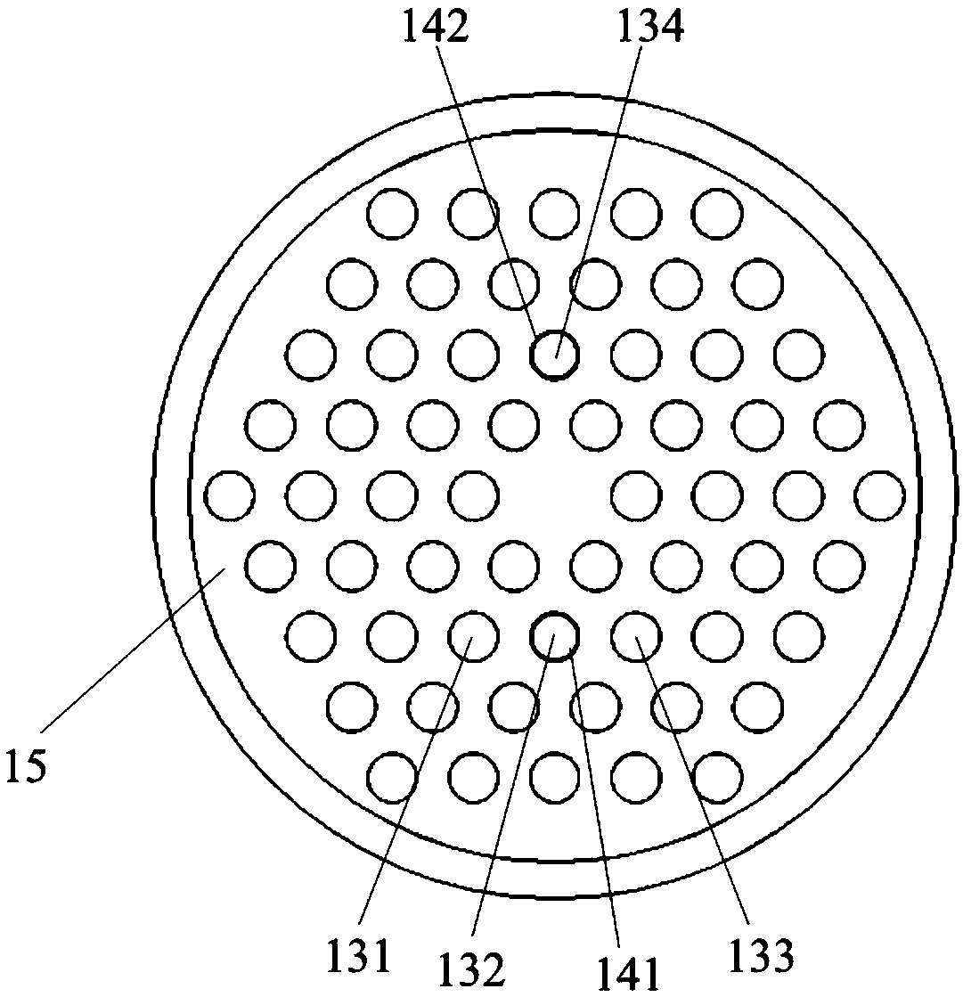
[0024] Such as figure 1 Shown is the structural diagram of the optical fiber temperature sensor based on surface plasmon resonance and strain compensation proposed by the present invention. The optical fiber temperature sensor based on surface plasmon resonance and strain compensation is composed of a protective sleeve 11 and a sensing optical fiber 12 . The protective sleeve 11 has an outer diameter of 1mm and is made of quartz material, and is used to protect the sensing optical fiber from damage such as breakage caused by the environment under test. Such as figure 2 A structural diagram of the sensing fiber 12 is shown. Sensing optical fiber 12 is made up of ...


PUM

PropertyMeasurementUnit
Thicknessaaaaaaaaaa

Abstract

The invention belongs to the technical field of photoelectric detection, and presents an optical fiber temperature sensor based on surface plasmon resonance and strain compensation. A sensing fiber isa solid photonic crystal fiber. Dielectric holes of the photonic crystal fiber are distributed in a regular hexagonal shape and in multiple layers with the fiber core as the center. The inner walls of the two dielectric holes in the centers of the opposite sides of the second hexagonal dielectric hole layer from the fiber core are coated with metal films, and the metal films are made of a metal material capable of generating surface plasmon resonance. One of the dielectric holes coated with the metal films and two adjacent dielectric holes in the same layer are filled with a dielectric A, andthe refractive index of the dielectric A is negatively correlated with temperature. All the dielectric holes not filled with the dielectric A are filled with a dielectric B, and the refractive indexof the dielectric B is not affected by temperature. The problem that the accuracy of measurement results is affected by strain in temperature sensing is solved. The temperature sensor is corrosion-resistant and not susceptible to electromagnetic interference, and can be used in harsh detection environments.

Description

technical field [0001] The invention belongs to the technical field of photoelectric detection and relates to an optical fiber temperature sensor based on surface plasmon resonance and strain compensation. Background technique [0002] In many production links in petrochemical, steel, nuclear power and other industrial fields, the accurate measurement of temperature value is not only related to production quality, but also related to production safety. Because electronic temperature sensing equipment cannot be used in environments with high explosion-proof requirements, strong electromagnetic interference, and strong corrosion, and optical fiber equipment has the characteristics of intrinsic safety, anti-electromagnetic interference, and strong corrosion resistance, so optical fiber temperature sensing technology has become One of the important directions of temperature sensing. At present, fiber optic temperature sensing methods mainly use fiber gratings and fiber resonato...

Claims


Application Information

Patent Timeline
IPC IPC(8): G01K11/32
CPCG01K11/3206
Inventor 韩博陆科
Owner 辽宁省计量科学研究院
Learn More