
Automatic sampling device of new-type oil storage tank

An automatic sampling device and oil storage tank technology, applied in sampling devices, sampling, measuring devices, etc., can solve the problems of high labor intensity, affected sample quality, oil leakage to the top of the oil tank, etc., to reduce the labor of workers. The effect of strength, sampling work saving time and effort, and convenient sampling operation

Pending Publication Date: 2019-01-01
李茂华
View PDF9 Cites 0 Cited by
  • Summary
  • Abstract
  • Description
  • Claims
  • Application Information

AI Technical Summary

Problems solved by technology

Problems in manual sampling: (1) The accuracy of the sampling position is poor, and the oil level of each oil tank is different
When sampling, use the sampling rope according to experience, and place the sampling bottle at the corresponding position. The human error is large and the randomness is large; (2) The safety of sampling is poor. Manual sampling must be taken from the sampling hole at the top of the tank. In case of rain, snow, strong wind, Weather such as sand and dust brings risks to the operation of sampling personnel
At the same time, there is a large electrostatic hazard in the sampling of light oil products. If the human body is not discharged according to the operation of static electricity in each link of the manual sampling process, it will cause fire and explosion hazards; During the sampling process, it is inevitable that the oil will leak to the top of the oil tank during the sampling operation, and the oil will remain along the top of the oil tank from the tank wall, polluting the tank body; (4) The quality of the sample is affected. The cap of the sampling bottle must be opened before sampling the affected oil tank, and it is inevitable to enter the sampling bottle in case of dust, rain and snow; (5) The work intensity is high. The sampling personnel must climb to the top of the tank every time they take a sample. The labor intensity is high and the sampling time is long. low efficiency

Method used


Image

  • Automatic sampling device of new-type oil storage tank
  • Automatic sampling device of new-type oil storage tank
  • Automatic sampling device of new-type oil storage tank

Examples


Embodiment Construction

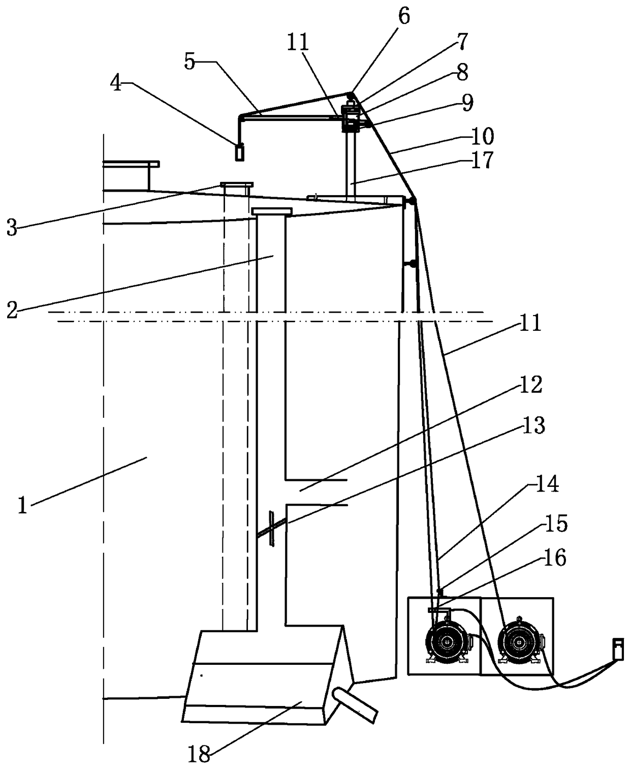
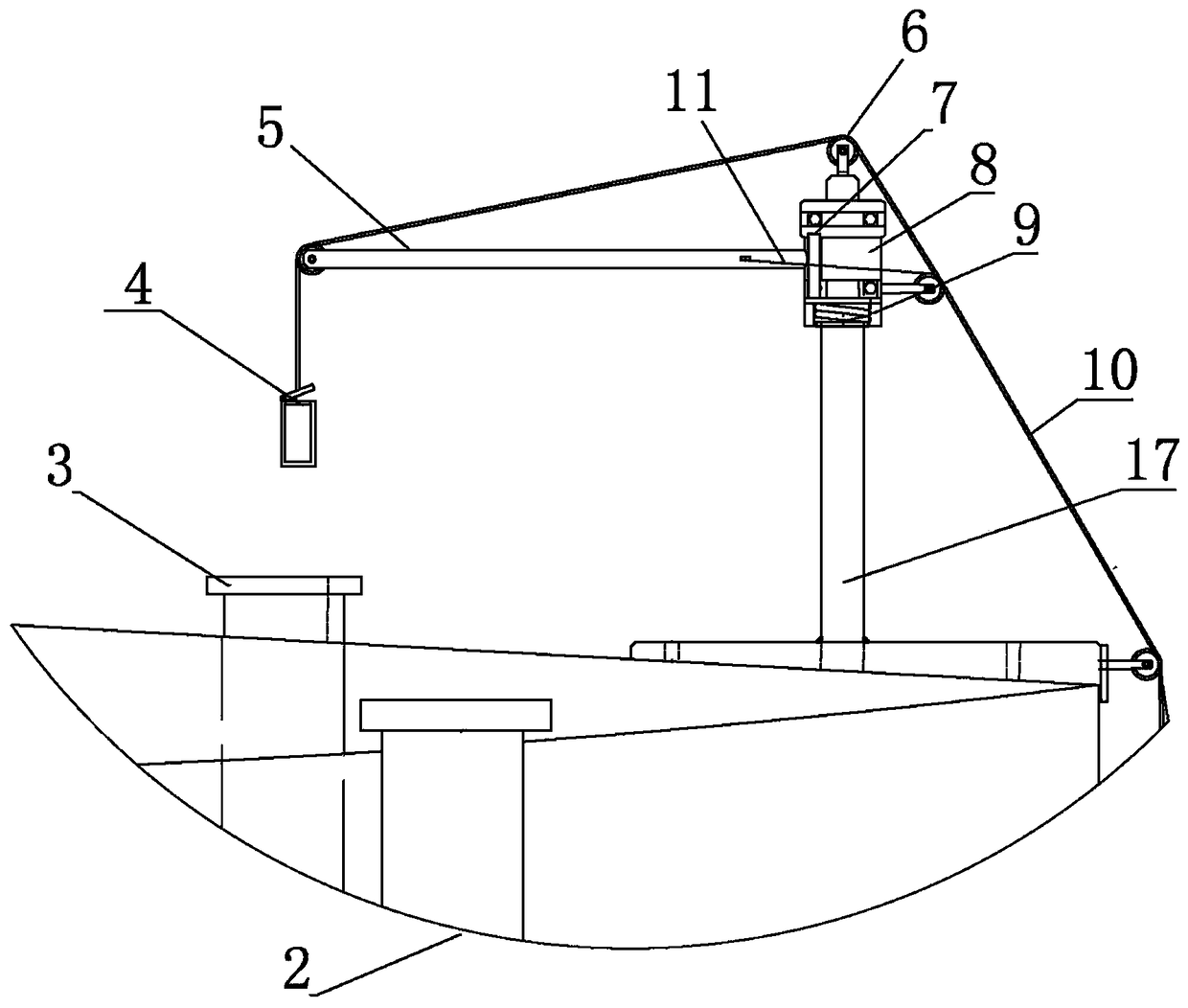
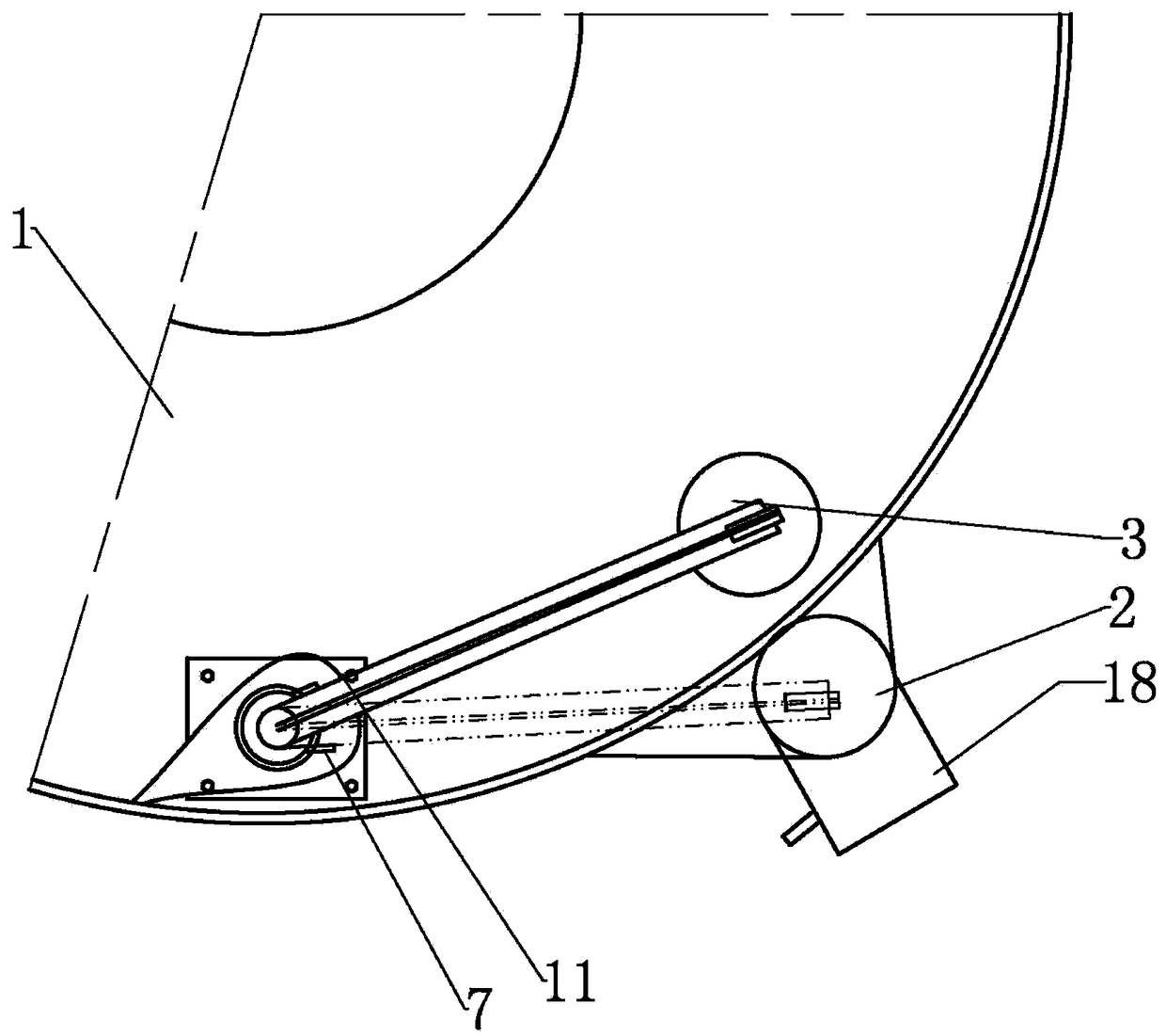
[0011] A new type of automatic sampling device for oil storage tanks, such as figure 1 , figure 2 , image 3 As shown, including frame column 17, meter counter 16, three steel wire ropes and two motors, frame column 17 is vertically installed on the top surface of oil tank 1 by mounting seat. A T-shaped swing arm 5 is installed on the top of the frame column 17 through horizontally arranged bearings, and one end of the swing arm 5 is provided with two fixed pulleys. The other end of the swing arm forms a vertically arranged rotating shaft 8, a reset torsion spring 9 is set on the lower end of the rotating shaft 8, a bearing is also arranged on the top of the rotating shaft, and a double groove fixed pulley 6 is installed on the top of the rotating shaft through the bearing. A swing arm limit plate 7 is respectively arranged on both sides of the 17 top, and a swing arm stay rope 11 is connected on the side wall of the swing arm. The drum is connected; the motor 20 drum rota...


PUM


Abstract

The invention discloses an automatic sampling device of a new-type oil storage tank. A machine frame column is installed on the top face of an oil tank. The top end of the machine frame column is provided with a swing arm. One end of the swing arm is provided with two fixed pulleys. The top end of a rotating shaft is provided with a double-groove fixed pulley device. Each of two sides of the top end of the machine frame column is respectively provided with a swing arm limiting plate. One side wall of the swing arm is connected with a swing arm pull rope connected with a winding drum installedon the rotating shaft of a motor. A sampling box is connected below the free end of the swing arm through two steel wire ropes. A box body of the sampling box is connected with one steel wire rope, and a box cover of the sampling box is connected with the other steel wire rope. The two steel wire ropes are respectively connected with the winding drum installed on the rotating shaft of the other motor across the double-groove fixed pulley. The steel wire rope connected with the box body of the sampling box passes through a meter counter. The other steel wire rope connected with the box cover ofthe sampling box passes through a through hole in a Z-shaped component. The outer side wall of the oil tank is vertically provided with a sample discharging pipe. The lower end of the sample discharging pipe is connected with a sampling pool.

Description

technical field [0001] The invention relates to a novel automatic sampling device for an oil storage tank. Background technique [0002] Sampling conditions of crude oil storage tanks: 1. Risk identification: 1. Toxic and harmful gases: hydrogen sulfide gas at the sampling port can reach up to 300ppm; Risk of falling; 3. Burns: The temperature of the oil in the degreasing tank of the special second unit can reach a maximum of 105°C, and there is a risk of scalding when sampling; 2. Introduction to sampling: the first unit: settling tank: tanking twice a week, temporary tanking in special cases Sampling; Purified oil tanks and buffer tanks: daily tank sampling and measurement; special couplet: settling tank: once every five days; deoiling tank: once a week; purified oil tanks, sampling once every time oil is delivered; In case of production fluctuations, the joint station needs to encrypt samples and increase the workload of employees. In case of bad weather, personnel cann...

Claims


Application Information

Patent Timeline
Patent Type & Authority Applications(China)
IPC IPC(8): G01N1/10
CPCG01N1/10G01N2001/1031
Inventor 杜黎航王科科邱江源陈永鹏李茂华
Owner 李茂华
Learn More