
Ultrasonic detection method for bonding quality

A technology for ultrasonic detection and bonding quality, which is applied in the analysis of solids using sound waves/ultrasonic waves/infrasonic waves, etc. It can solve problems such as the difficulty in determining the side where debonding occurs, the difficulty in distinguishing the leading edge of composite blades, and the inconsistent thickness of the leading edge of the blade. , to achieve the effect of high reliability, high reliability and fast scanning

Active Publication Date: 2019-01-01
AEROSPACE INST OF ADVANCED MATERIALS & PROCESSING TECH
View PDF10 Cites 7 Cited by
  • Summary
  • Abstract
  • Description
  • Claims
  • Application Information

AI Technical Summary

Problems solved by technology

At present, ultrasonic testing is a commonly used non-destructive testing method. However, when the conventional ultrasonic testing method is used to test the bonding quality of the above structure, due to the particularity of the above structure (such as irregular and thin wrapping, inconsistent thickness of the leading edge of the blade, etc.) ), there will be the following problems: the metal wrapping is difficult to distinguish, the irregular shape of the wrapping is difficult to couple, the debonding of the wrapping is difficult to distinguish from the defects in the leading edge of the composite blade, and it is difficult to determine which side of the debonding occurs, which seriously affects the test results

Method used


Image

  • Ultrasonic detection method for bonding quality
  • Ultrasonic detection method for bonding quality
  • Ultrasonic detection method for bonding quality

Examples


Embodiment 1

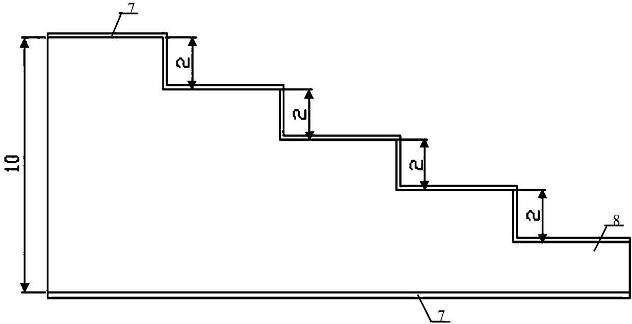
[0042] Taking the method of the present invention to realize the ultrasonic detection of the bonding quality of the leading edge of a CFRP composite blade with a thickness of 2 to 10 mm and the nickel alloy wrapping skin with a thickness of 0.2 mm as an example, the steps are as follows:

[0043] 1. Exclude defective composite material blades at the leading edge before wrapping:

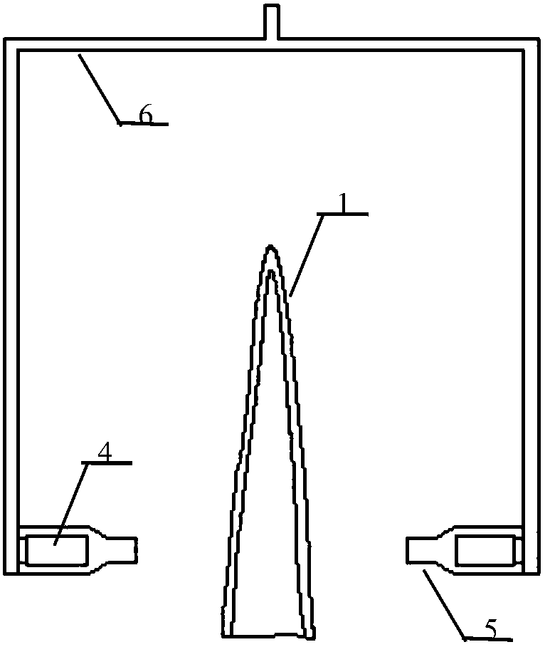
[0044] (1) see figure 1 and 2, using ultrasonic water spray penetrating C-scan automatic scanning equipment for scanning, this equipment includes ultrasonic probe 4, water spray jacket 5, probe arm 6, the frequency of transmitting and receiving ultrasonic probe 4 is 2.25MHz, which can ensure sufficient Ultrasonic energy penetrates the inspected part and can ensure high detection sensitivity; the scanning step is 1mm, the C-scan scanning direction 3 is perpendicular to the direction of the leading edge, and the C-scan stepping direction 2 is parallel to the direction of the leading edge, ensuring hig...


PUM

PropertyMeasurementUnit
diameteraaaaaaaaaa
thicknessaaaaaaaaaa
diameteraaaaaaaaaa

Abstract

The invention provides an ultrasonic detection method for bonding quality. The ultrasonic detection method comprises: 1, before the front edge of a composite material blade is not bonded to a metal overlap, detecting the front edge position by using an ultrasonic water spraying penetration C scanning method, and eliminating the composite material blade with the defect at the front edge position; 2, after the composite material blade with the defect-free front edge is bonded to a metal overlap, detecting the blade overlapping position by using the ultrasonic water spraying penetration C scanning method, determining the horizontal position of the debonding defect, and marking; and 3, respectively detecting the front surface and the back surface of the marking position by using a high-resolution retarding block probe, and through the height of the reflected ultrasonic wave pulse formed by the composite material / metal / air interface wave of the surface, determining the surface at which thedebonding defect is generated. With the method of the present invention, the debonding defect with the diameter of not more than 5 mm can be rapidly and accurately detected, the surface at which the debonding is generated can be accurately determined, and the design and rework requirements of the product can be met.

Description

technical field [0001] The invention relates to an ultrasonic detection method for bonding quality, in particular to an ultrasonic detection method for the bonding quality of a resin-based composite blade leading edge and a small-thickness metal wrapping, and belongs to the field of ultrasonic nondestructive testing. Background technique [0002] New engine blades have begun to use a new structure of fiber-reinforced resin-based composite materials bonded with small-thickness metal wrapping to replace pure metal blades, which can greatly reduce the weight of the blades. However, the hemming in this structure will be washed by high temperature and high-speed airflow during use. If the bonding quality is not good, the hemming will fall off and enter the engine, causing major accidents. Therefore, effective nondestructive testing technology must be used to detect it. Check the bonding quality. [0003] In the above blade structure, the thickness of the metal wrapping is ≤0.3 m...

Claims


Application Information

Patent Timeline
Patent Type & Authority Applications(China)
IPC IPC(8): G01N29/04
CPCG01N29/04
Inventor 高晓进江柏红贺锁让王国帅李晋平周金帅
Owner AEROSPACE INST OF ADVANCED MATERIALS & PROCESSING TECH
Learn More