
Motor

A technology of motors and magnets, applied in electromechanical devices, conversion sensor output, instruments, etc., can solve problems such as influence, achieve the effect of enhancing shielding effect and reducing angle error

Active Publication Date: 2019-01-01
NIDEC SANKYO CORP
View PDF7 Cites 10 Cited by
  • Summary
  • Abstract
  • Description
  • Claims
  • Application Information

AI Technical Summary

Problems solved by technology

In addition, there may be such a problem that the output of the magnetic sensor and the amplification value of the output of the magnetic sensor formed by the encoder circuit mounted on the substrate are affected by the frame ground noise of the motor body to which the encoder is fixed, power supply noise, etc. Effect of noise

Method used


Image

  • Motor
  • Motor
  • Motor

Examples


Embodiment Construction

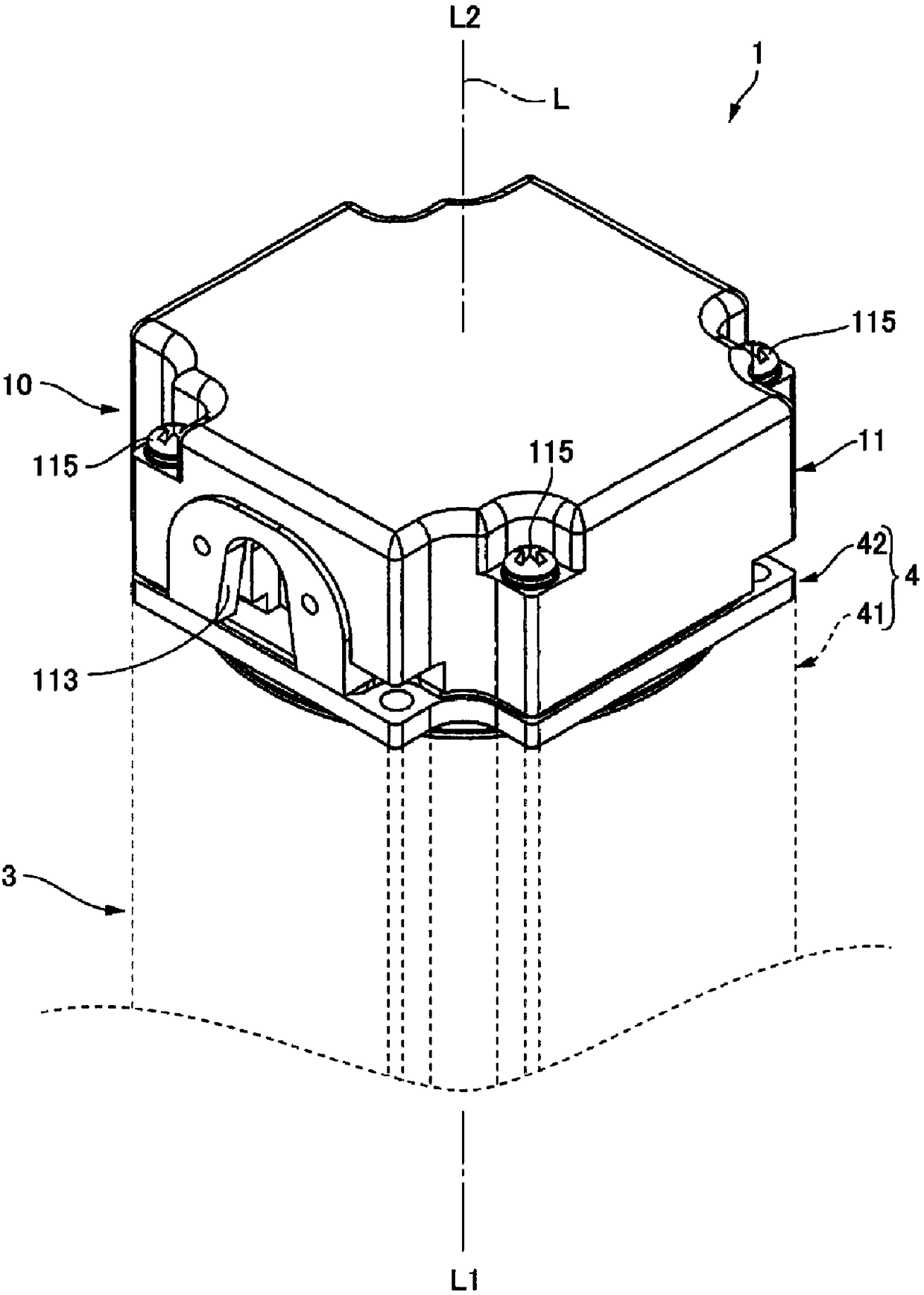
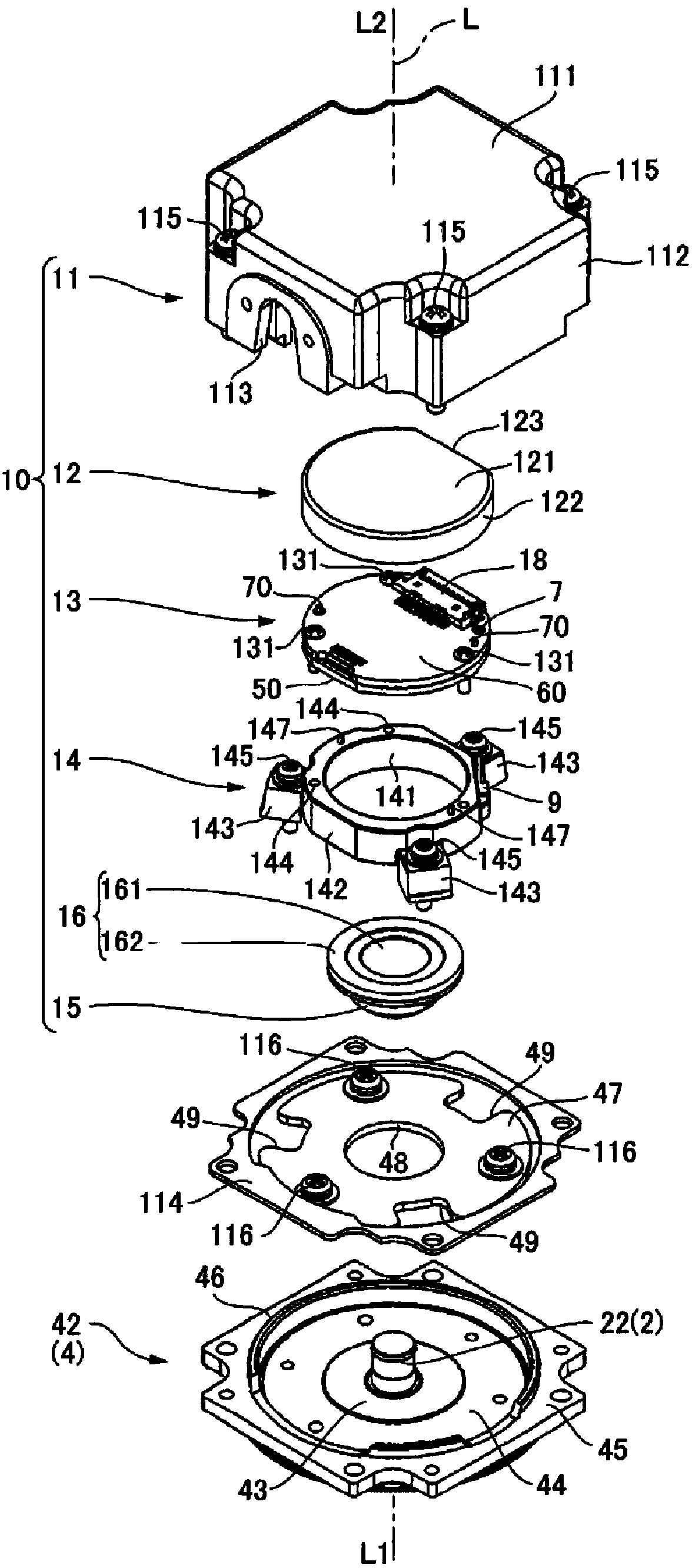
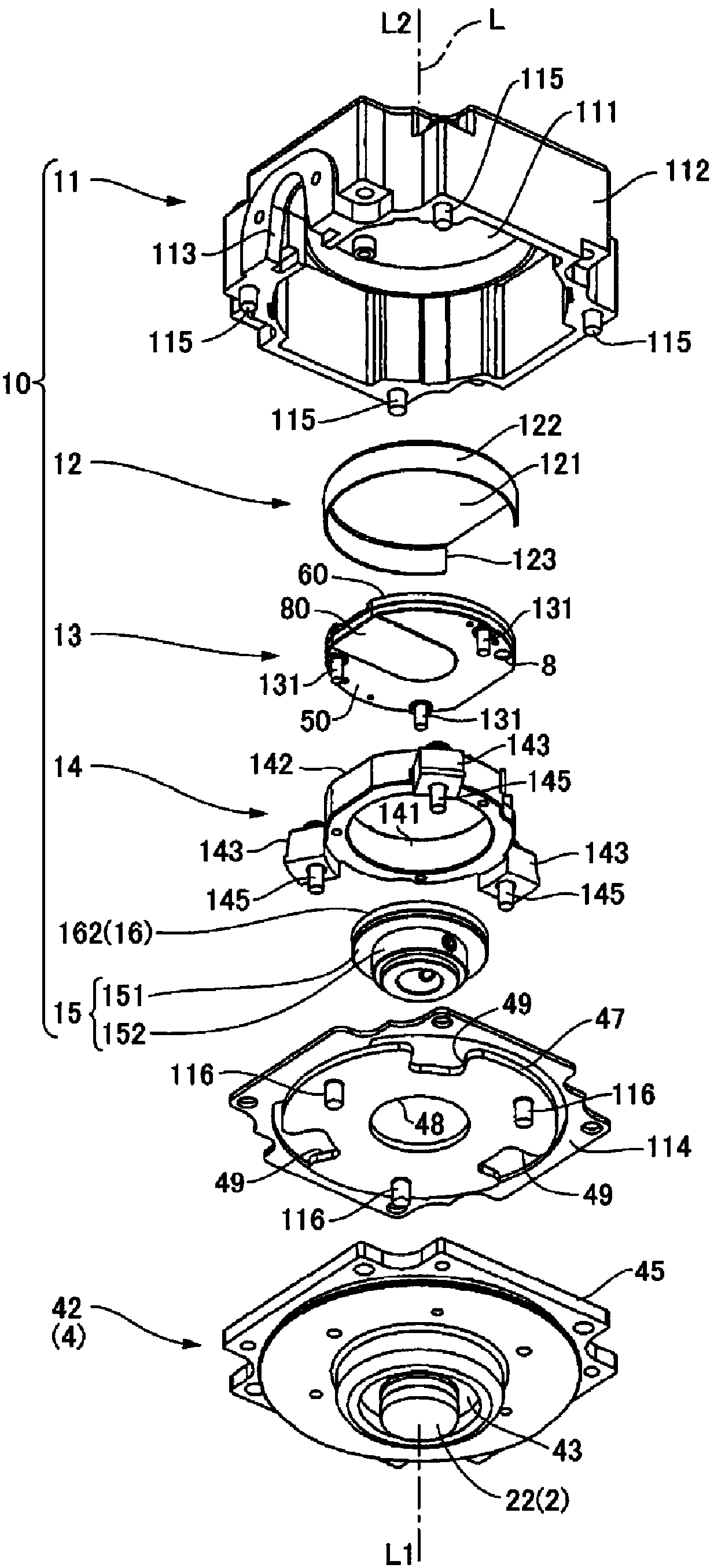
[0036] Hereinafter, embodiments of a motor to which the present invention is applied will be described with reference to the drawings. figure 1 It is a perspective view showing the appearance of the end portion of the motor 1 to which the present invention is applied, on the side of the encoder 10 . figure 2 , image 3 is an exploded perspective view of the encoder 10 and the bearing cage 42, figure 2 is an exploded perspective view viewed from the opposite side of the output, image 3 This is an exploded perspective view viewed from the output side. Figure 4 It is a sectional view of the encoder 10 and the bearing holder 42 .

[0037] (the whole frame)

[0038] The motor 1 includes: a rotating shaft 2 (refer to Figure 4 ) of the motor body 3; and an encoder 10 that detects the rotation of the rotary shaft 2. The motor body 3 includes a motor case 4 that accommodates a rotor and a stator (not shown). The rotor rotates integrally with the rotating shaft 2 . One end ...


PUM


Abstract

A motor can reduce the influence of magnetic noise, electromagnetic wave noise and electrical noise on a coder. The motor (1) may include a coder (10) configured to detect rotation of a turning shaft(2). The coder (10) comprises a substrate (60) equipped with a magneto sensitive element (17). The substrate (60) is coated with a substrate holding rack (50) being in signal grounding electrical connection with the coder circuit from the magnet (16) size, and one side, opposite to the substrate holding rack (50) is coated with a first shielding part (12) of signal grounding level, and a second shielding part (80) of the magneto sensitive element (17) fixedly coats the substrate holding rack (50). The substrate (60) is completely covered by the part of the signal grounding level, and the magneto sensitive element (17) and the coder can completely shield electrical noise. The motor can enhance the shielding effect on the magnetic noise and the electromagnetic wave noise and can enhance theshielding effect of the electrical noise.

Description

technical field [0001] The present invention relates to a motor having an encoder for detecting the rotation of a rotor by a magnetic sensor. Background technique [0002] Patent Document 1 discloses a motor having an encoder for detecting rotation of a rotor. In the motor of Patent Document 1, the encoder includes: a magnetic sensor mounted on a substrate; and a magnet that rotates integrally with an output shaft of the motor. The substrate is supported by a holder fixed to the motor case. The substrate on which the magnetic sensor is installed and the magnet are covered with a cover member. The cover member is fixed to the inner surface of the encoder case, and the encoder case is fixed to the motor case. [0003] prior art literature [0004] Patent Document 1: Japanese Patent Laid-Open No. 2016-3888 Contents of the invention [0005] The technical problem to be solved by the invention [0006] Since the encoder mounted on the motor is affected by various noises, ...

Claims


Application Information

Patent Timeline
IPC IPC(8): H02K11/215H02K11/01
CPCH02K11/01H02K11/215G01D5/24433G01D5/2458H02K11/0141G01D5/245H02K1/2753H02K1/28H02K21/22H02K29/08H02K2211/03H02K11/40
Inventor 齋藤豊
Owner NIDEC SANKYO CORP
Learn More