Solar power generation device with cleaning function

A technology for power generation equipment and solar energy, applied in photovoltaic power generation, cleaning methods and tools, cleaning methods using tools, etc., can solve problems such as residual dirt, easy to be contaminated with dust, and affect the service life of photovoltaic panels, and achieve the effect of prolonging the service life

Inactive Publication Date: 2019-01-01
河南东润电子有限公司
View PDF6 Cites 18 Cited by
  • Summary
  • Abstract
  • Description
  • Claims
  • Application Information

AI Technical Summary

Problems solved by technology

[0004] At present, the photovoltaic panels in the existing photovoltaic power generation equipment are easy to be contaminated with dust and residual dirt after long-term use. If they are not cleaned in time, the service life of the photovoltaic panels will be affected

Method used


Image

  • Solar power generation device with cleaning function
  • Solar power generation device with cleaning function
  • Solar power generation device with cleaning function

Examples


Embodiment 1

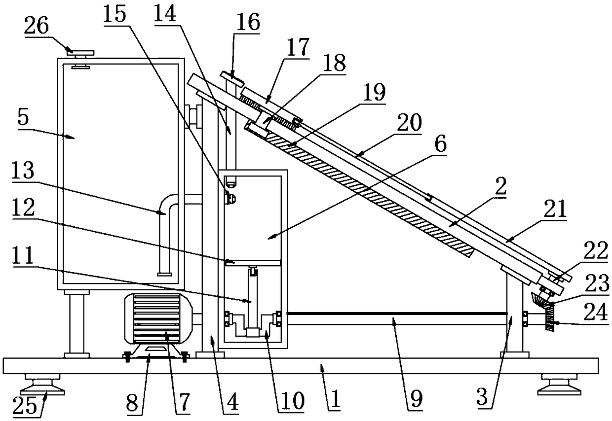
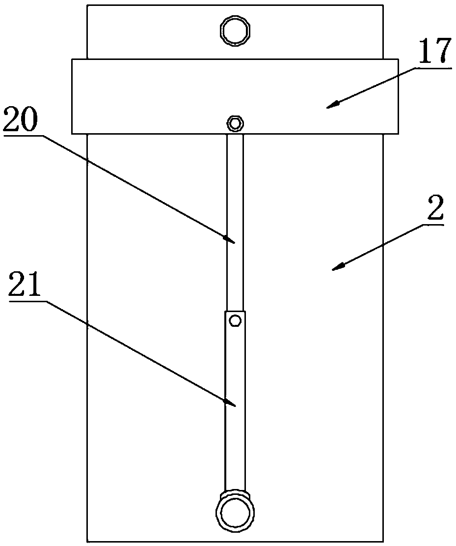
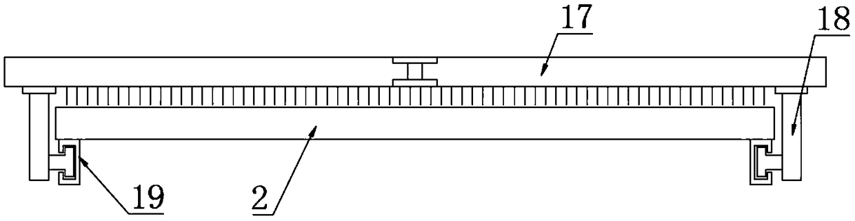
[0022] see Figure 1~3 , in an embodiment of the present invention, a solar power generation device with a cleaning function includes a base plate 1, a photovoltaic panel 2, a water tank 5, a pumping chamber 6, a driving motor 7, a drive shaft 9 and a cleaning brush 17; The two sides are respectively fixedly connected to the second support 4 and the first support 3, and the upper ends of the second support 4 and the first support 3 are respectively fixedly connected to the left and right sides of the photovoltaic panel 2, the photovoltaic panel 2 is inclined, and the drive motor is arranged on the upper left side of the bottom plate 1 7. The lower end of the driving motor 7 is fixedly connected to the motor base 8, the motor base 8 is fixedly connected to the base plate 1, and the wires of the driving motor 7 are connected to the power supply and the switch. The right side of the driving motor 7 is connected to the driving shaft 9, and the driving shaft 9 passes through the A ...

Embodiment 2

[0026] see Figure 1~3 , in an embodiment of the present invention, a solar power generation device with a cleaning function includes a base plate 1, a photovoltaic panel 2, a water tank 5, a pumping chamber 6, a driving motor 7, a drive shaft 9 and a cleaning brush 17; The two sides are respectively fixedly connected to the second support 4 and the first support 3, and the upper ends of the second support 4 and the first support 3 are respectively fixedly connected to the left and right sides of the photovoltaic panel 2, the photovoltaic panel 2 is inclined, and the drive motor is arranged on the upper left side of the bottom plate 1 7. The lower end of the driving motor 7 is fixedly connected to the motor base 8, the motor base 8 is fixedly connected to the base plate 1, and the wires of the driving motor 7 are connected to the power supply and the switch. The right side of the driving motor 7 is connected to the driving shaft 9, and the driving shaft 9 passes through the A ...


PUM


Abstract

The invention discloses a solar power generation device with a cleaning function. The solar power generation device with a cleaning function is characterized in that the right side of a drive motor isrotatably connected to a driving shaft; the driving shaft passes through a first bracket and a second bracket and is rotatably connected with bearings of the first bracket and the second bracket; a water tank is arranged at the upper part of the driving motor; the water tank is fixedly connected to a bottom plate and the second bracket; the right side of the second bracket is fixedly connected toa pumping chamber; the left part of the driving shaft is fixedly connected with a crankshaft; the crankshaft is located at the lower part of the pumping chamber and passes through the side wall of the pumping chamber; the middle part of the crankshaft sleeves the lower part of a connecting rod; the upper end of the connecting rod is rotatably connected with a piston plate; the edge of the pistonplate is in sliding connection to the inner wall of the pumping chamber in a sealed manner; the left wall of the upper part of the pumping chamber is provided with a water inlet pipe; the water inletpipe is communicated with the bottom of the water tank; and the upper part of the pumping chamber is connected with a water outlet pipe. For the solar power generation device with a cleaning function,the piston plate is driven by the rotating crankshaft to reciprocate up and down so as to pump the water liquid in the water tank to spray to the upper surface of a photovoltaic panel, and in the water spraying process, a swinging rod is driven by a driving rod to drive a clean brush to reciprocate up and down along a guide groove, thus achieving the effect of cleaning and brushing.

Description

technical field [0001] The invention relates to a new energy power generation component, in particular to a solar power generation device with a cleaning function. Background technique [0002] The main principle of photovoltaic power generation is the photoelectric effect of semiconductors. When a photon irradiates a metal, its energy can be completely absorbed by an electron in the metal. The energy absorbed by the electron is large enough to overcome the internal gravitational force of the metal to do work, escape from the metal surface, and become a photoelectron. Silicon atoms have 4 outer electrons. If atoms with 5 outer electrons, such as phosphorus atoms, are added to pure silicon, they will become N-type semiconductors; if pure silicon is doped with atoms with 3 outer electrons, such as Boron atoms form a P-type semiconductor. When the P-type and N-type are combined, the contact surface will form a potential difference and become a solar cell. When sunlight irrad...

Claims


Application Information

Patent Timeline
Patent Type & Authority Applications(China)
IPC IPC(8): H02S40/10B08B3/02B08B1/00
CPCB08B1/002B08B1/008B08B3/02H02S40/10Y02E10/50
Inventor 王丹凤
Owner 河南东润电子有限公司
Why Eureka
Try Eureka