Heat radiation device for low-voltage control box of new energy vehicle

A new energy vehicle, low-voltage control technology, applied in the direction of cooling/ventilation/heating transformation, electrical components, electrical equipment structural parts, etc., can solve the problems of low heat dissipation efficiency, lack of heat dissipation structure, easy to cause fire, etc., to improve heat dissipation Efficiency and the effect of prolonging the service life

Active Publication Date: 2019-01-01
台州市皓仔邦工业设计有限公司
View PDF10 Cites 2 Cited by
  • Summary
  • Abstract
  • Description
  • Claims
  • Application Information

AI Technical Summary

Problems solved by technology

The low-voltage control box of new energy vehicles usually lacks an effective heat dissipation structure, the heat dissipation efficiency is low, and it is easy to cause fire, etc. Therefore, it is necessary to provide a low-voltage control box for new energy vehicles. The patent includes a control box shell and a control box bottom plate arranged at the bottom of the control box shell, the open end of the control box shell is set towards the control box bottom plate, and the top two ends of the control box shell are provided with Two heat dissipation chambers, the top of the heat dissipation chamber is provided with a motor mounting seat, the motor mounting seat is provided with a motor, and the side wall of the heat dissipation chamber facing the inside of the control box housing is provided with a wiring hole. Two power supply fixtures are arranged symmetrically above the inside of the control box housing between the two heat dissipation chambers. The power supply fixtures include a connecting column vertically connected to the top of the control box housing, and connected to The end of the column, the bearing plate extending to the inside of the control box housing, the bearing plate is provided with a power supply, the motor is connected to the power supply through the wiring hole, the output shaft of the motor is connected to a fan, The air outlet direction of the fan is towards the bottom of the control box housing, the bottom of the heat dissipation chamber is provided with an air outlet corresponding to the air outlet direction of the fan, the bottom of the heat dissipation chamber is provided with a guide plate, and the air guide The plate is inclined to the outside of the control box housing, the front of the control box housing is provided with a main heat dissipation net cover corresponding to the position of the power supply, and the end surface of the control box housing is provided with an auxiliary heat dissipation grill at the position corresponding to the deflector. Net cover, although the structure of this invention is simple, there are many deficiencies and defects. In the existing equipment, the design of the fan has defects. and the fan is in the control box, once it is damaged, it will be inconvenient to replace and maintain, which will increase the workload of the staff, make the staff easy to feel physical fatigue, and at the same time reduce the work efficiency. In view of these situations, in order to avoid the above technical problems, It is indeed necessary to provide a heat dissipation device for the low-voltage control box of a new energy vehicle to overcome the defects in the prior art

Method used


Image

  • Heat radiation device for low-voltage control box of new energy vehicle
  • Heat radiation device for low-voltage control box of new energy vehicle
  • Heat radiation device for low-voltage control box of new energy vehicle

Examples


Embodiment Construction

[0024] The technical solutions in the embodiments of the present invention will be clearly and completely described below in conjunction with the accompanying drawings in the embodiments of the present invention. Obviously, the described embodiments are only some of the embodiments of the present invention, not all of them. Based on the embodiments of the present invention, all other embodiments obtained by persons of ordinary skill in the art without creative work all belong to the protection scope of the present invention.

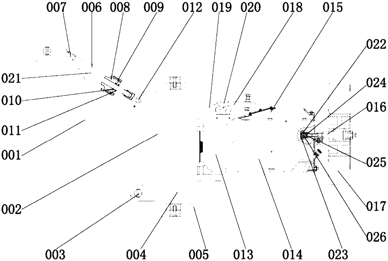
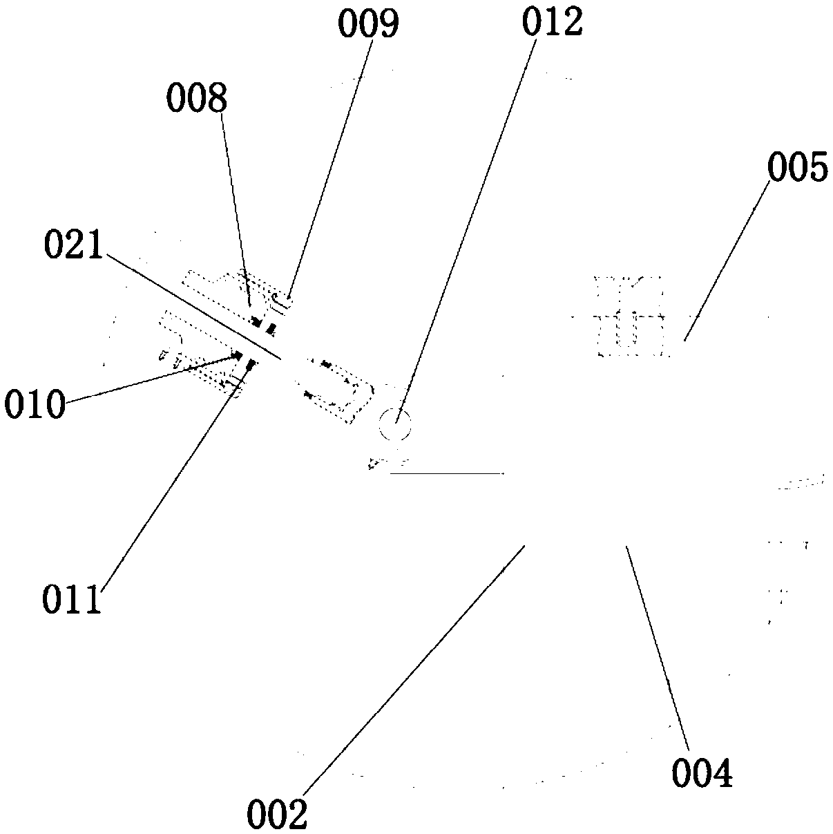
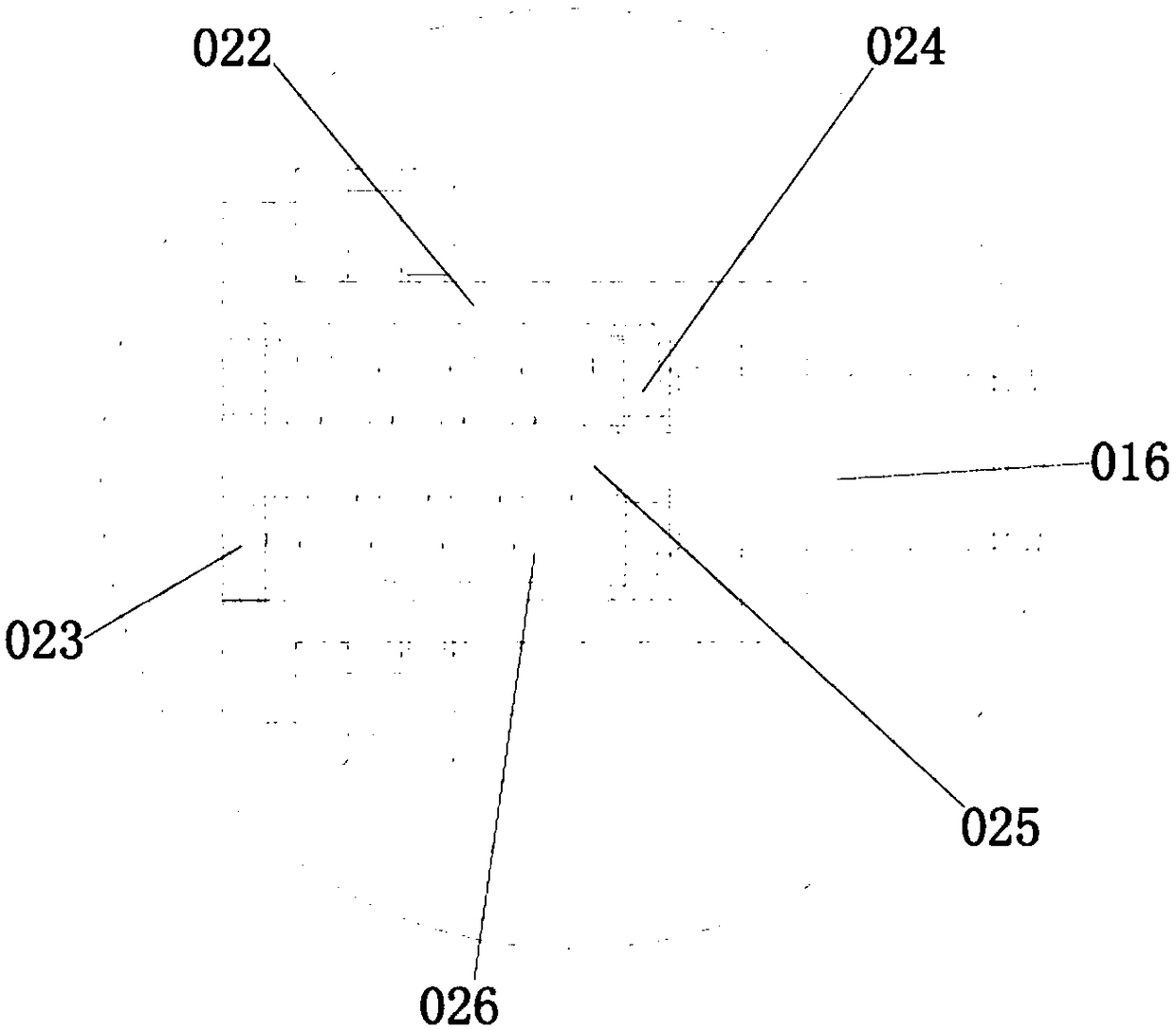
[0025] see Figure 1-3, the present invention provides a technical solution: a heat dissipation device for a low-voltage control box of a new energy vehicle, including a box body 001, a motor 014 is installed and fixed, a sleeve rod 006 is installed on the inner wall of the box body 001, a push rod 021 is fixed and the base is adjusted The inclination angle of 002, the outer wall of the sleeve rod 006 is sleeved with the sleeve cover 009, the end of the ...


PUM


Abstract

The invention discloses a heat radiation device for a low-voltage control box of a new energy vehicle. The heat radiation device includes a box body, wherein the inner wall of the box body is providedwith a sleeve rod; the inner wall of the sleeve rod is provided with a bottom block; a top block is arranged at the right side of the bottom block; the inner wall of the top block is provided with apush rod; the outer wall of the push rod is provided with a latch; the outer wall of the latch is provided with a base; the inner wall of the base is provided with a top seat; the outer wall of the right side of the top seat is provided with a fixed block; the outer wall of the left side of the fixed block is connected with the outer wall of the right side of the top seat; the outer wall of the right side of the fixed block is provided with a motor; the inner wall of the motor is provided with a rotating shaft; the outer wall of the rotating shaft is connected to the inner wall of the motor; the outer wall of the rotating shaft is provided with a fan blade; and the inner wall of the fan blade is connected with the outer wall of the rotating shaft. For the heat radiation device for a low-voltage control box of a new energy vehicle, through coordination among the sleeve rod, the push rod and the latch, under the effect of the base and the top seat, the sleeve rod fixes the push rod in the sleeve rod, so that the push rod can slide inside the sleeve rod so as to adjust the inclination angle of the base, so that the heat radiation device for a low-voltage control box of a new energy vehicle is suitable for promotion and application.

Description

technical field [0001] The invention relates to the technical field of new energy vehicles, in particular to a cooling device for a low-voltage control box of a new energy vehicle. Background technique [0002] New energy vehicles refer to the use of unconventional vehicle fuels as power sources or the use of conventional vehicle fuels, the use of new vehicle power devices, the integration of advanced technologies in vehicle power control and drive, and the formation of advanced technical principles and new technologies. , New structure cars, new energy vehicles include hybrid vehicles, pure electric vehicles, fuel cell vehicles, hydrogen engine vehicles, gas vehicles, alcohol ether vehicles and so on. The low-voltage control box of new energy vehicles usually lacks an effective heat dissipation structure, the heat dissipation efficiency is low, and it is easy to cause fire, etc. Therefore, it is necessary to provide a low-voltage control box for new energy vehicles. The pa...

Claims


Application Information

Patent Timeline
Patent Type & Authority Applications(China)
IPC IPC(8): H05K7/20
CPCH05K7/20863
Inventor 陈功鸿
Owner 台州市皓仔邦工业设计有限公司
Why Eureka
Try Eureka