
Electronic product recycling device

A technology for recycling and electronic products, applied in grain processing, non-rotational vibration suppression, etc., can solve problems such as energy waste, high device load, and difficult crushing, achieve good crushing effect, reduce separation costs, and reduce workpiece loss and the effect on energy consumption

Inactive Publication Date: 2019-01-04
苏州和必尔斯电子科技有限公司
View PDF0 Cites 2 Cited by
  • Summary
  • Abstract
  • Description
  • Claims
  • Application Information

AI Technical Summary

Problems solved by technology

[0003] Existing waste materials for electronic products mainly include non-metallic elements such as plastic and glass, and metal elements such as gold, silver, copper, iron, and aluminum. Among them, iron has relatively high hardness and toughness, and it is difficult to crush. Most product recovery devices do not pre-separate iron, and directly crush iron together with other elements, which not only puts a high load on the device, but also causes waste of energy

Method used


Image

  • Electronic product recycling device
  • Electronic product recycling device
  • Electronic product recycling device

Examples


Embodiment 1

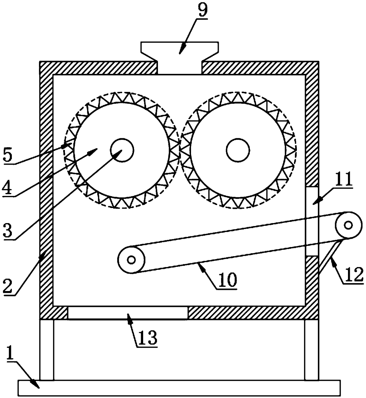
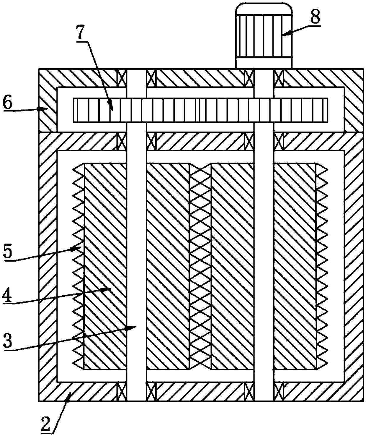
[0021] see Figure 1~2 , an electronic product recovery processing device, comprising a base 1, the top of the base 1 is fixed with a crushing box 2 through a bracket; the top of the crushing box 2 is provided with a feeding hopper 9; There are two left and right rotating shafts 3, and the left and right rotating shafts 3 are respectively connected to the front and rear walls of the crushing box 2 in rotation. The left and right rotating shafts 3 are located in the inner part of the crushing box 2 and are fixedly equipped with crushing rollers 4. The side walls of the crushing rollers 4 are evenly equipped with a number of crushing teeth 5, so that Improve the crushing effect; the rear wall of the crushing box 2 is fixedly equipped with a gear box 6, the rear end of the rotating shaft 3 passes through the rear wall of the gear box 6 and is rotationally connected with the rear wall of the gear box 6, and the left and right rotating shafts 3 are fixed in the gear box 6 Gears 7 m...

Embodiment 2

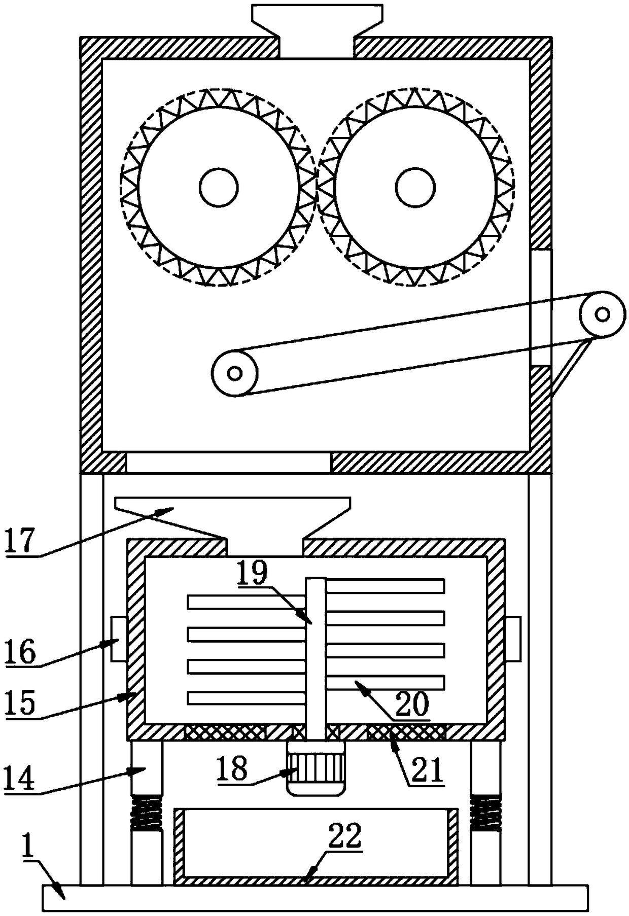
[0023] see image 3 , on the basis of embodiment 1, a crushing barrel 15 is also provided above the base 1, and the crushing barrel 15 is located below the crushing box 2. The bottom of the crushing barrel 15 is fixedly connected with a pole 14, and the bottom end of the pole 14 is connected to the base 1 fixedly connected, the pole 14 includes three sections, the upper and lower sections are round rods, the middle section is a spring, and the upper and lower ends of the spring are fixedly connected with the upper and lower round rods respectively, so that the crushing bucket 15 can vibrate; the crushing bucket 15 The top is fixedly connected with a hopper 17, the hopper 17 is located below the discharge port 13, the non-magnetic material falls into the crushing bucket 15 through the hopper 17, and the bottom wall of the crushing bucket 15 is rotatably connected with a second rotating shaft 19 through a sealed bearing. A number of crushing blades 20 are fixedly installed on th...


PUM


Abstract

The invention relates to the technical field of electronic product processing, particularly to an electronic product recycling device. The electronic product recycling device comprises a base, and thetop of the base is fixedly provided with a crushing box through a support; in the forth-back direction inside the crushing box, two rotating shafts are arranged and rotatingly connected with the front and rear walls of the crushing box, the parts of left-right rotating shafts inside the crushing box are all fixedly provided with crushing rollers, and the side wall of every crushing roller is uniformly provided with a plurality of crushing teeth; the internal bottom of the crushing box is fixedly provided with a conveying belt mechanism, which is inclined towards the left top; the right end ofthe conveying belt mechanism penetrates through the right wall of the crushing box and out of the crushing box; the conveying belt of the conveying belt mechanism is made of soft magnets. According to the electronic product recycling device, magnetic materials contained inside crushed electronic products such as iron materials can be attracted to the conveying belt and move along with the conveying belt towards the right top and then out of the crushing box, so that the iron materials can be separated from the electronic products, further subsequent crushing operation can be facilitated, andworkpiece wearing and energy consumption as well as separating costs can be reduced.

Description

technical field [0001] The invention relates to the technical field of electronic product processing, in particular to an electronic product recovery processing device. Background technique [0002] Electronic products are related products based on electric energy, mainly including: watches, smart phones, telephones, televisions, DVD players, video recorders, camcorders, radios, tape recorders, combination speakers, CD players, computers, mobile communication products, etc. . The materials used in electronic products are generally of high value. After electronic products are damaged, electronic products are often recycled. The existing recycling prevention mainly involves dismantling electronic products. Except for some components that can be directly recycled, the rest Pulverize, and then extract useful elements from the pulverized electronic fragments. [0003] Existing waste materials for electronic products mainly include non-metallic elements such as plastic and glass...

Claims


Application Information

Patent Timeline
Patent Type & Authority Applications(China)
IPC IPC(8): B02C4/08B02C23/08B02C18/12B02C18/16F16F15/06
CPCB02C4/08B02C18/0084B02C18/12B02C18/16B02C23/08B02C2201/06F16F15/06
Inventor 王康
Owner 苏州和必尔斯电子科技有限公司
Learn More