
Casting method of hydraulic valve casting

A technology for hydraulic valves and castings, applied in casting molding equipment, casting molds, casting mold components, etc., can solve the problems of high scrap rate, difficulty in fast, accurate molding, and complex casting processes.

Inactive Publication Date: 2019-01-04
KOCEL INTELLIGENT FOUNDRY IND INNOVATION CENT CO LTD
View PDF8 Cites 8 Cited by
  • Summary
  • Abstract
  • Description
  • Claims
  • Application Information

AI Technical Summary

Problems solved by technology

[0003] Aiming at the problems of complex casting process, heavy workload, high scrap rate and difficulty in quick and accurate molding of existing hydraulic valve castings, the present invention provides a casting method for hydraulic valve castings. Combine with the outer core as a whole, through reasonable parting and integration, reduce more than 30 sand cores to 3 sand molds, and then use 3D sand printing to print and combine the 3 sand molds separately. Through this casting method The application of hydraulic valves can obtain hydraulic valves whose size and surface accuracy meet the standard requirements.

Method used


Image

  • Casting method of hydraulic valve casting
  • Casting method of hydraulic valve casting
  • Casting method of hydraulic valve casting

Examples


Embodiment 1

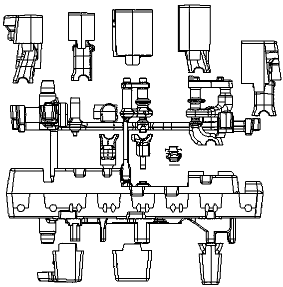
[0030] A casting method for hydraulic valve castings, such as Figure 2 to Figure 6 Shown include:

[0031] S01: Design the core including the hydraulic valve: design the casting process of the hydraulic valve through three-dimensional drawing software, and design the core of the hydraulic valve according to the casting process.

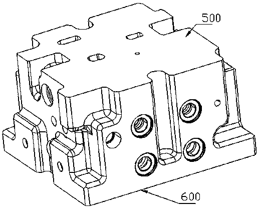
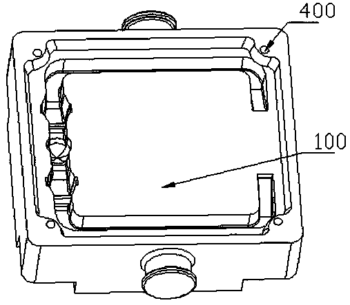
[0032] S02: If Figure 2-Figure 6 As shown, the bottom surface 600 of the hydraulic valve and the top surface 500 of the hydraulic valve are selected as the splitting surfaces of the core to split the core into a bottom core 100 , a middle core 200 and an upper cover core 300 .

[0033] The bottom core 100 includes all bottom surfaces and gating system structures of the hydraulic valve.

[0034] The intermediate core includes all external structures and intermediate inner cavity structures between the bottom surface and the top surface of the hydraulic valve. The middle core integrates all the internal cavity sand cores of the hydraulic valve and ...

Embodiment 2

[0048] A casting method for hydraulic valve castings, such as Figure 2 to Figure 6 Shown include:

[0049]S01: Design the core including the hydraulic valve: design the casting process of the hydraulic valve through three-dimensional drawing software, and design the core of the hydraulic valve according to the casting process.

[0050] S02: Select the bottom surface 600 of the hydraulic valve and the top surface 500 of the hydraulic valve as the splitting surfaces of the core to split the core into a bottom core 100 , a middle core 200 and an upper cover core 300 .

[0051] The bottom core 100 includes all bottom surfaces and gating system structures of the hydraulic valve.

[0052] The intermediate core includes all external structures and intermediate inner cavity structures between the bottom surface and the top surface of the hydraulic valve. The middle core integrates all the internal cavity sand cores of the hydraulic valve and all structures and external structures o...


PUM

PropertyMeasurementUnit
Granularityaaaaaaaaaa

Abstract

The invention relates to a casting method of a hydraulic valve casting. The casting method is characterized by comprising the following steps: designing a mold core including a hydraulic valve; selecting the bottom surface of the hydraulic valve and the top surface of the hydraulic valve as split surfaces of the mold core and dividing the mold core into a bottom core, an intermediate core and an upper cover core; printing the intermediate core by adopting a 3D printer; printing the bottom core and the upper cover core by adopting the 3D printer and / or preparing the bottom core and the upper cover core by adopting a wooden pattern; assembling the bottom core and the intermediate core; assembling the upper cover core on the intermediate core. The casting method of the hydraulic valve casting, provided by the invention, has the benefits that the intermediate core of the hydraulic valve and the external contour are combined together, so that the quantity of sand cores is reduced, and the process step is simplified; through the integrated design of the intermediate core, the sand core strength of the intermediate valve core is enhanced, so that the problems of sand core deformation andthe like are solved.

Description

technical field [0001] The invention belongs to the technical field of casting, and in particular relates to a casting method of hydraulic valve castings. Background technique [0002] Hydraulic control valves (referred to as hydraulic valves) refer to components used in hydraulic transmission systems or hydraulic control systems to control fluid pressure, flow and direction. In the existing process of casting and producing hydraulic valves, due to the thick outer wall structure of the hydraulic valve and the small size of the middle valve core, it is difficult to form an internal structure. The usual solution is to divide the middle valve core into parts such as figure 1 The multiple sand cores shown are produced by a hot core box. This process has many procedures and a large workload, which is easy to cause damage to the sand cores, resulting in unstable product quality, high scrap rate, and the combined surface between the sand cores is in the casting process. A batch of...

Claims


Application Information

Patent Timeline
IPC IPC(8): B22C1/22B22C9/10B22C9/24
CPCB22C1/22B22C9/103B22C9/24
Inventor 李朝东李栋马步强梁继亚
Owner KOCEL INTELLIGENT FOUNDRY IND INNOVATION CENT CO LTD
Learn More