High pressure holding furnace of low pressure casting machine

A low-pressure casting machine and holding furnace technology, applied in the field of casting, can solve the problems that product quality cannot be guaranteed, heating and heat preservation heat conduction efficiency is low, and high-strength castings cannot be satisfied, so as to achieve convenient setting and gating system optimization, increase temperature, increase intensity effect

Inactive Publication Date: 2019-01-04
SHANDONG FUTONG ELECTRIC
View PDF0 Cites 3 Cited by
  • Summary
  • Abstract
  • Description
  • Claims
  • Application Information

AI Technical Summary

Problems solved by technology

[0002] At present, the general-purpose low-pressure casting machine holding furnace is generally heated by radiant silicon carbide rods. The furnace chamber is not only used as a storage room for aluminum liquid, but also as a heating chamber and a pressurized chamber. The silicon carbide rods are heated, and the heat is transmitted through radiation and air conduction. To ensure a constant temperature of molten aluminum in the furnace, this kind of holding furnace plays a key role in the application of low-pressure casting machines, but with the development requirements of casting technology, there are some problems and shortcomings
First, during the production process, the heating and heat preservation heat conduction efficiency in the furnace is low, which increases the power consumption; second, during the production process, the furnace is filled and discharged with compressed air cyclically. increase, the castings will have defects such as pores; third, the current holding furnace filling and holding pressure is only 0.2MPa, and the holding pressure of the casting is low, which cannot meet high-strength castings; The gas content increases without degassing, so that the product quality cannot be guaranteed

Method used


Image

  • High pressure holding furnace of low pressure casting machine
  • High pressure holding furnace of low pressure casting machine
  • High pressure holding furnace of low pressure casting machine

Examples


Embodiment Construction

[0031] In order to facilitate the understanding of those skilled in the art, the present invention will be further described below in conjunction with the accompanying drawings.

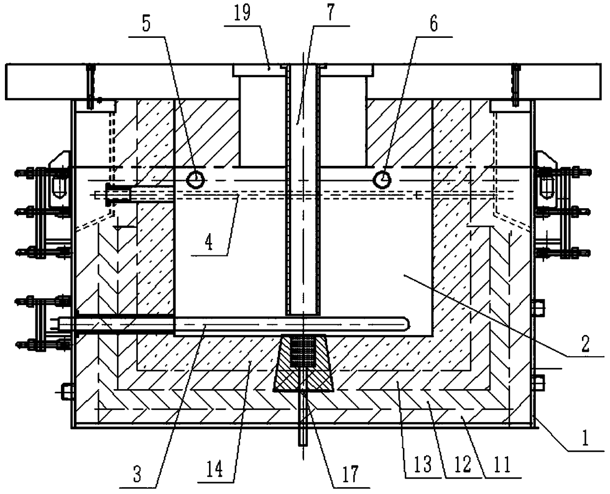
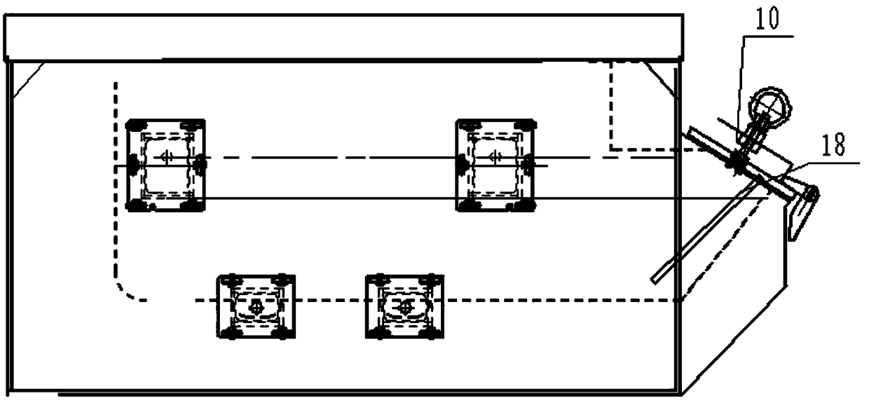
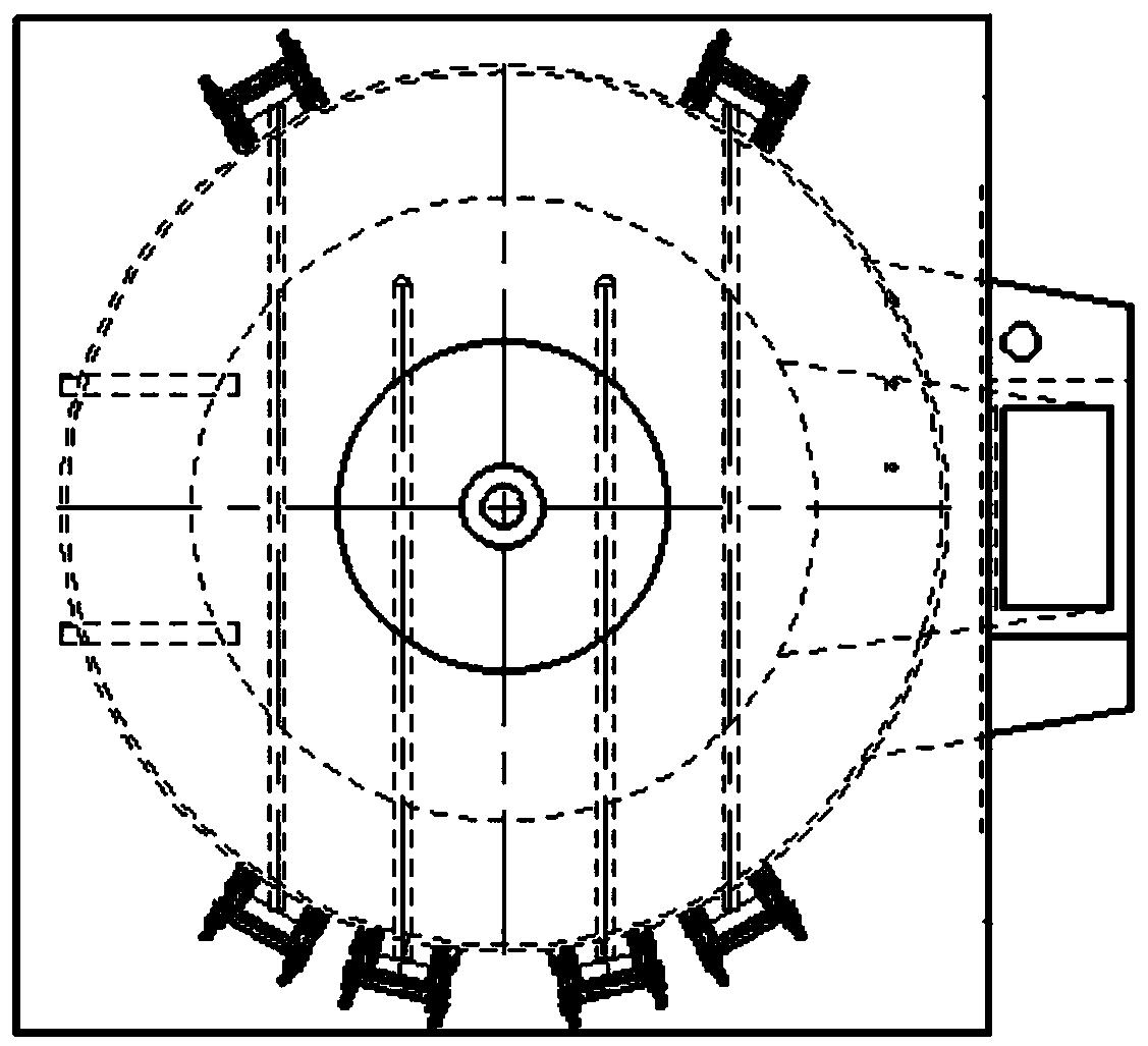
[0032] Such as Figure 1 to Figure 4 As shown, a high-pressure holding furnace for a low-pressure casting machine includes a holding furnace shell 1, a sealable pressurized chamber 2 is arranged inside the holding furnace shell 1, and an aluminum addition port 10 of the holding furnace shell 1 is arranged on the holding furnace shell On the side wall of the body 1 and communicated with the pressurized chamber 2, the top of the holding furnace shell 1 is provided with a liquid riser, and the liquid riser is provided with a riser pipe 7 to communicate with the pressurized chamber 2, and the aluminum liquid is in the pressurized chamber 2 , by pressurizing the pressurization chamber 2, the aluminum is hydraulically injected into the riser pipe 7, and connected with the casting mold through the riser pip...


PUM


Abstract

The invention discloses a high pressure holding furnace of a low pressure casting machine and belongs to the technical field of casting. The high pressure holding furnace of the low pressure casting machine comprises a holding furnace shell; a sealable pressurized chamber is formed in the holding furnace shell; a liquid lifting opening is formed in the top of the holding furnace shell; a liquid lifting tube communicating with the pressurized chamber is arranged in the liquid lifting opening; a nitrogen pressurizing inlet and a nitrogen depressurizing outlet are also formed in the holding furnace shell; the nitrogen pressurizing inlet and the nitrogen depressurizing outlet both communicate with the pressurized chamber; a nitrogen pressure mechanism is arranged between the nitrogen pressurizing inlet and the nitrogen depressurizing outlet; the nitrogen pressure mechanism provides nitrogen for the nitrogen pressurizing inlet and recycles nitrogen from the nitrogen depressurizing outlet; the high pressure holding furnace of the low pressure casting machine further comprises a plurality of radiation heaters and immersion type heaters; the radiation heaters extend into the pressurized chamber and indirectly heat an aluminum liquid above the aluminum liquid; and the immersion type heaters extend into the pressurized chamber and directly heat the interior of the aluminum liquid.

Description

technical field [0001] The invention relates to the field of casting technology, in particular to a high-pressure holding furnace for a low-pressure casting machine. Background technique [0002] At present, the general-purpose low-pressure casting machine holding furnace is generally heated by radiant silicon carbide rods. The furnace chamber is not only used as a storage room for aluminum liquid, but also as a heating chamber and a pressurized chamber. The silicon carbide rods are heated, and the heat is transmitted through radiation and air conduction. This kind of holding furnace plays a key role in the application of low-pressure casting machines to ensure a constant temperature of molten aluminum in the furnace. However, with the development of casting technology, there are some problems and shortcomings. First, during the production process, the heating and heat preservation heat conduction efficiency in the furnace is low, which increases the power consumption; secon...

Claims


Application Information

Patent Timeline
Patent Type & Authority Applications(China)
IPC IPC(8): B22D18/04C22B21/06
CPCB22D18/04C22B21/064
Inventor 徐红军
Owner SHANDONG FUTONG ELECTRIC
Why Eureka
Try Eureka