Imaging positioning processing method based on small coaxial laser processing system

A technology of laser processing and processing methods, applied in metal processing equipment, laser welding equipment, manufacturing tools, etc., can solve the problems of low cutting efficiency, small field of view, small cutting field of view, etc., to improve cutting efficiency, fast moving speed, The effect of saving moving time

Active Publication Date: 2021-06-22
CHANGZHOU INNO MACHINING +1
View PDF0 Cites 0 Cited by
  • Summary
  • Abstract
  • Description
  • Claims
  • Application Information

AI Technical Summary

Problems solved by technology

[0004] Because the existing configuration of the small coaxial cutting scheme generally has a small field of view, and because the cutting field of view of the existing small coaxial cutting technology is small, the limit field of view is about 22*27, and this field of view can only cut one product in a cutting cycle. , each time a product is cut, the product needs to be moved, and the time for the product to move is relatively long, resulting in low cutting efficiency. Therefore, there is an urgent need for an imaging positioning process based on a small coaxial laser processing system to improve cutting efficiency. method

Method used


Image

  • Imaging positioning processing method based on small coaxial laser processing system
  • Imaging positioning processing method based on small coaxial laser processing system

Examples


Embodiment 1

[0030] In a specific embodiment, the step S20 specifically includes,

[0031] The image processing module converts the cutting positions of the first product to be cut and the second product to be cut into laser coordinates;

[0032] And respectively add the laser coordinates of the cutting positions of the first product to be cut and the second product to be cut to the corresponding offset and the fixed deviation caused by the deflection of the laser galvanometer to obtain the cutting trajectory of the first product to be cut and the second product to be cut .

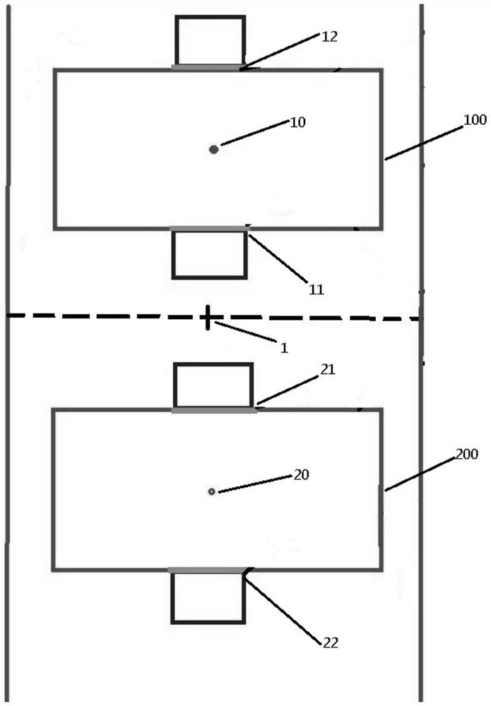
[0033] In this embodiment, the cutting positions 11 and 12 of the first product to be cut and the cutting positions 21 and 22 of the second product to be cut are two straight lines respectively, after converting into laser coordinates, the offsets between the center of the field of view and the real center of the product are added respectively Quantity, to get the cutting track of the first product to be cut and the ...

Embodiment 2

[0035] In a specific embodiment, the step S10 specifically includes,

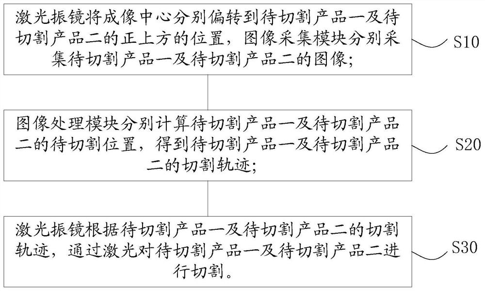
[0036] S11. The laser galvanometer deflects the imaging center from the zero position to the position directly above the product to be cut, and the image acquisition module collects the image of the product to be cut;

[0037] S12. The laser galvanometer deflects the imaging center from the position directly above the first product to be cut to the position directly above the second product to be cut, and the image acquisition module collects the image of the second product to be cut.

[0038] In this embodiment, the laser galvanometer first deflects the imaging center from the zero position to the position directly above the product 100 to be cut, triggers the image acquisition module to collect the image of the product 100 to be cut, and then the laser galvanometer quickly moves the imaging center To the top of the product 200 to be cut, the image acquisition module is triggered to collect the image of th...

Embodiment 3

[0040] In a specific embodiment, after the image acquisition module acquires the image of the product 2 to be cut, the laser vibrating mirror deflects the imaging center to the zero position.

[0041] In this embodiment, after the image acquisition module collects the image of the product to be cut, the laser galvanometer deflects the imaging center back to the zero point position, and the image processing module calculates the positional relationship between the cutting position of the product and the zero point position to obtain the corresponding cutting trajectory .


PUM


Abstract

The invention provides an imaging positioning processing method based on a small coaxial laser processing system, which comprises the steps of: the laser galvanometer deflects the center of the field of view to the position directly above the first product to be cut and the second product to be cut, and an image acquisition module The images of the first product to be cut and the second product to be cut are collected respectively; the image processing module calculates the positions to be cut of the first product to be cut and the second product to be cut, and obtains the cutting trajectory of the first product to be cut and the second product to be cut; the laser processing system According to the cutting tracks of the first product to be cut and the second product to be cut, the first product to be cut and the second product to be cut are cut by the laser. According to the technical solution, by collecting the images of two products, the cutting trajectories of the corresponding products are calculated respectively, and the two products are cut in one cutting cycle, which saves the travel time of the products and improves the cutting efficiency.

Description

technical field [0001] The invention relates to an imaging positioning processing method, in particular to an imaging positioning processing method based on a small coaxial laser processing system. Background technique [0002] As the size of the product becomes smaller and smaller, it is necessary to reduce the damage to the raw material during the processing. Therefore, laser cutting came into being. As the factory has higher and higher requirements for the processing size of the product, the small coaxial laser processing system started to catch on. [0003] Compared with paraxial or pseudo-coaxial processing systems, small coaxial has natural advantages in processing. The visual positioning of small coaxial laser cutting has obvious advantages compared with traditional paraxial positioning systems. The optical path of small coaxial laser and the optical path of image system The combination of the two can avoid the temperature drift of the galvanometer. [0004] Because...

Claims


Application Information

Patent Timeline
Patent Type & Authority Patents(China)
IPC IPC(8): B23K26/082B23K26/03B23K26/38
CPCB23K26/032B23K26/38B23K26/082
Inventor 阮建周华秦国双
Owner CHANGZHOU INNO MACHINING
Why Eureka
Try Eureka