Vehicle fitting flywheel shell automatic treatment equipment and flywheel shell automatic treatment process

A technology for automatic processing and auto parts, applied in metal processing equipment, maintenance and safety accessories, manufacturing tools, etc., can solve the problems of high labor intensity, slow work efficiency, incomplete cleaning, etc., to reduce labor intensity and save time , the effect of improving work efficiency

Active Publication Date: 2019-01-04
江苏固诺新材料科技有限公司
View PDF10 Cites 4 Cited by
  • Summary
  • Abstract
  • Description
  • Claims
  • Application Information

AI Technical Summary

Problems solved by technology

[0003] In order to solve the above problems, the present invention provides an automatic processing equipment for the flywheel housing of auto parts and an automatic processing technology for the flywheel housing, which can solve the problem that the existing flywheel housing is not easy to accurately locate when clamping, and because the weight of the flywheel housing is heavy, the existing clamping The equipment is not easy to clamp, and it is easy to loosen during processing, which will cause damage to the surface of the flywheel shell. The personnel need to re-clamp the flywheel shell to process different positions of the flywheel shell, and manually clean the iron filings attached to the flywheel shell , Incomplete cleaning, long time consumption, high labor intensity and slow work efficiency, etc., can realize the function of automatic positioning and cleaning of the flywheel shell, multi-directional positioning of the flywheel shell, processing will not loosen, and the flywheel will not be loose when clamping The surface of the shell will not be damaged, automatic flipping, no need to re-clamp, automatic cleaning of iron filings in the flywheel shell, complete cleaning, short time consumption, and has the advantages of simple operation, low labor intensity and high work efficiency

Method used


Image

  • Vehicle fitting flywheel shell automatic treatment equipment and flywheel shell automatic treatment process
  • Vehicle fitting flywheel shell automatic treatment equipment and flywheel shell automatic treatment process
  • Vehicle fitting flywheel shell automatic treatment equipment and flywheel shell automatic treatment process

Examples


Embodiment Construction

[0034] In order to make the technical means, creative features, goals and effects achieved by the present invention easy to understand, the present invention will be further described below in conjunction with specific illustrations. It should be noted that, in the case of no conflict, the embodiments in the present application and the features in the embodiments can be combined with each other.

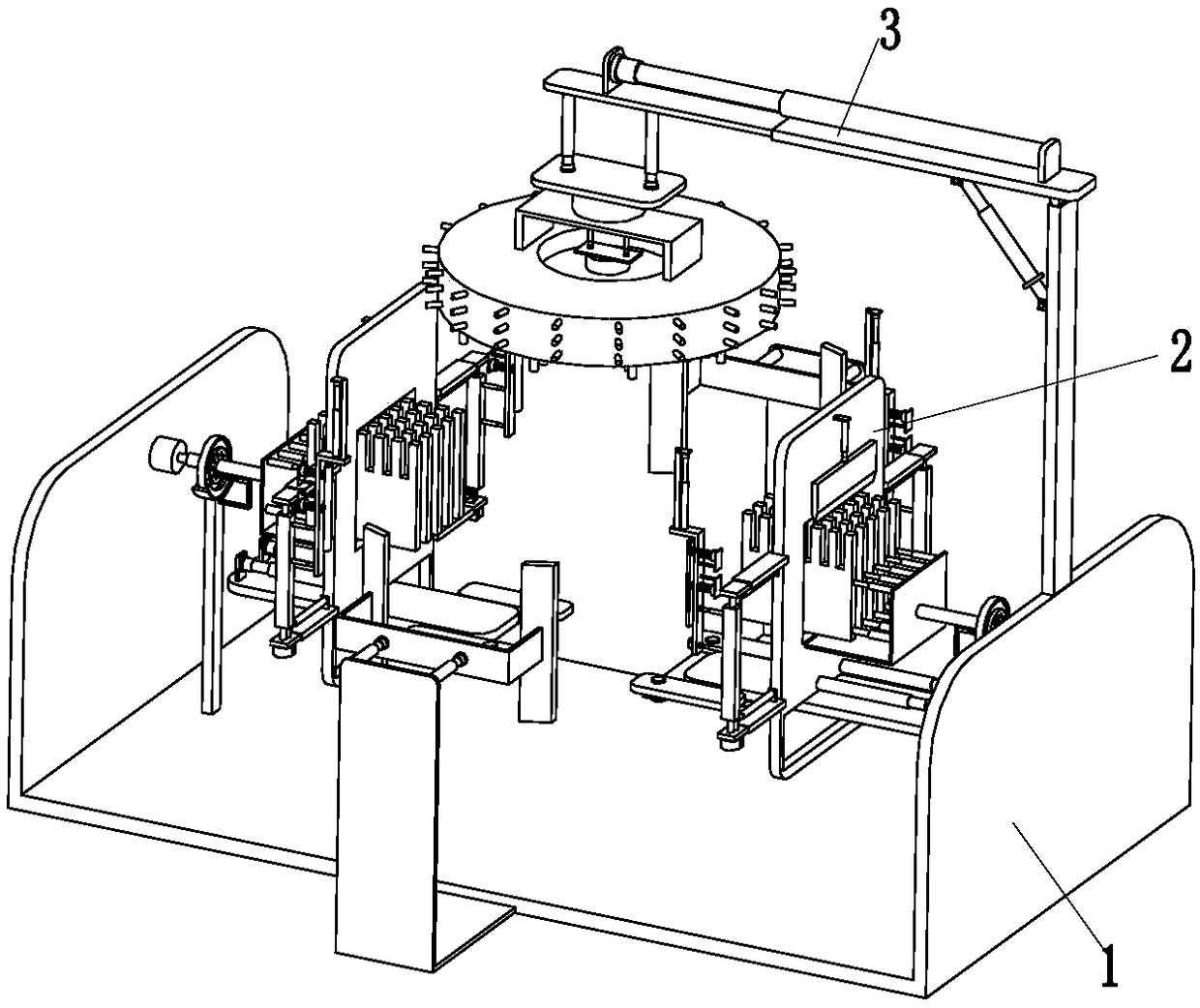
[0035] Such as Figure 1 to Figure 6 As shown, an automatic processing equipment for flywheel shells of auto parts includes a chassis 1, a positioning device 2 and a cleaning device 3. The positioning device 2 is installed on the upper end of the chassis 1, and the cleaning device 3 is installed on the right end of the chassis 1.

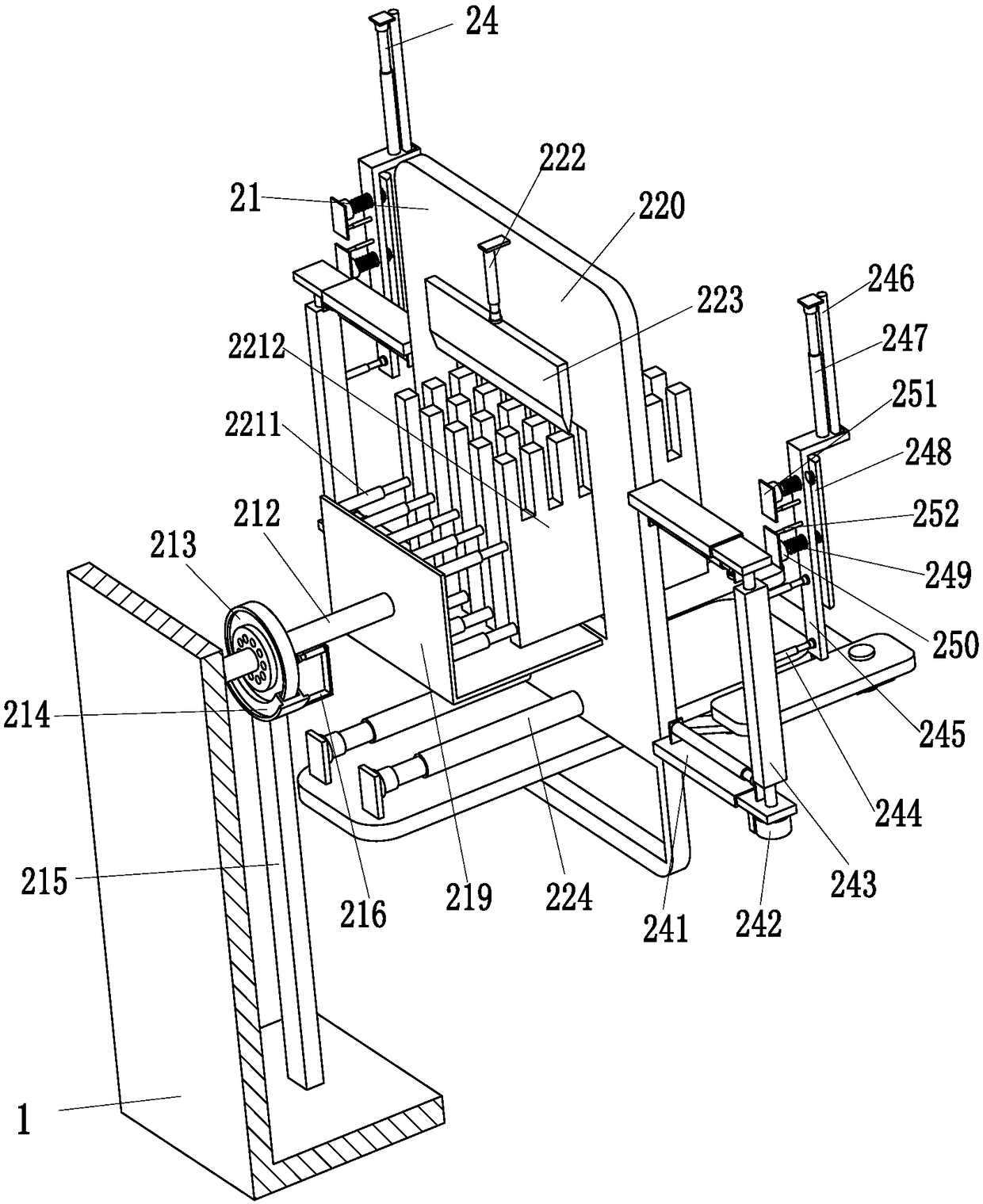
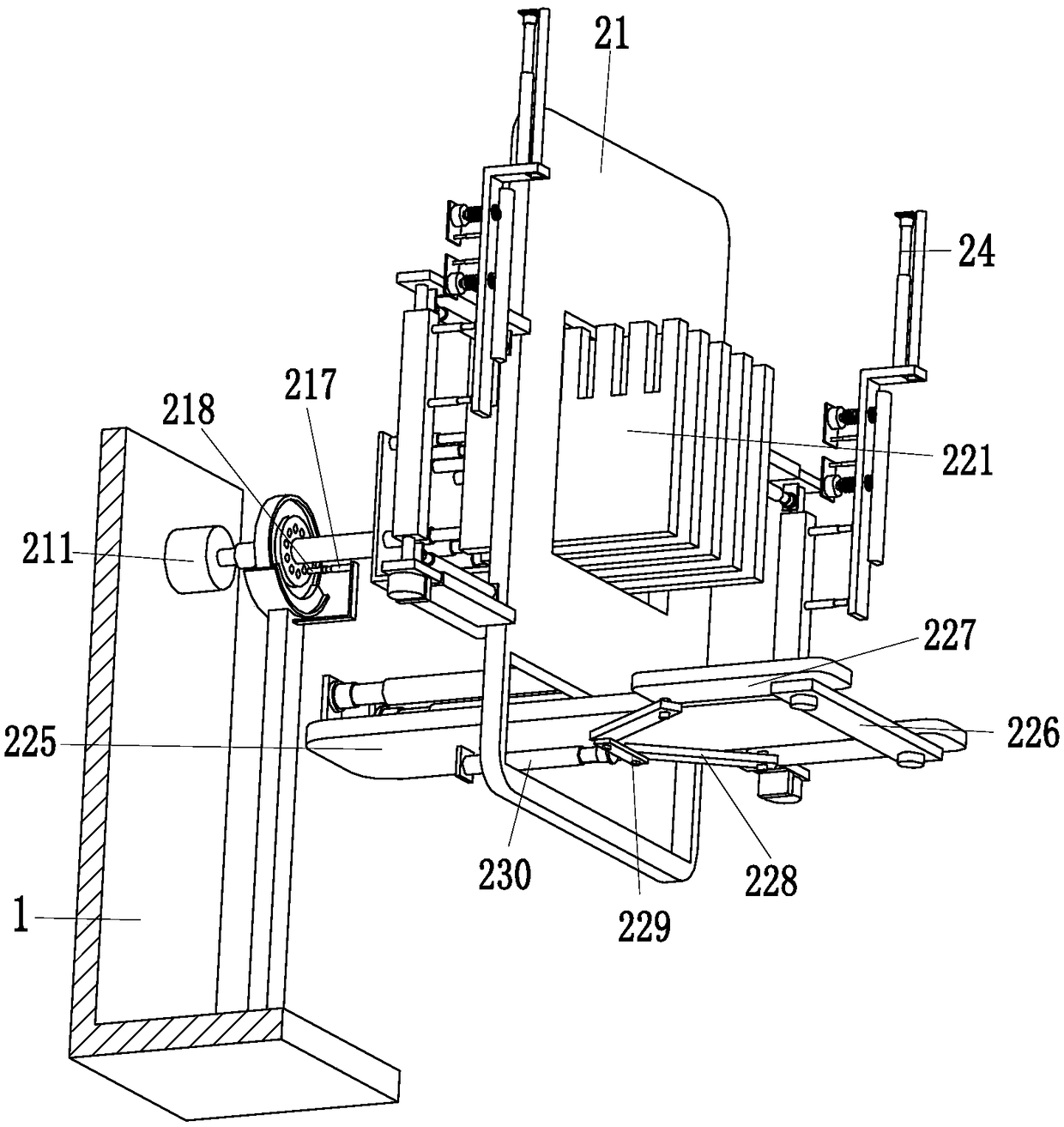
[0036] The positioning device 2 includes two lifting mechanisms 21, four clamping mechanisms 24 and two holding mechanisms 26. The two lifting mechanisms 21 are installed on the left and right ends of the underframe 1. The front and rear of the lifting mec...


PUM


Abstract

The invention relates to vehicle fitting flywheel shell automatic treatment equipment and a flywheel shell automatic treatment process. The equipment comprises a chassis, a positioning device and a cleaning device; the positioning device is mounted at the upper end of the chassis; and the cleaning device is mounted at the right end of the chassis. The equipment can solve the difficulties of difficult achievement of the positioning precision in traditional clamping of flywheel shells, difficult clamping of the flywheel shells by traditional clamping equipment due to higher weight of the flywheel shells, surface damage of the flywheel shells caused by easy looseness during machining, capability of machining different positions of the flywheel shells through renewed clamping of the flywheel shells by persons, halfway cleaning of iron chips attached in the flywheel shells through a manual mode, long consumed time, high labor intensity and low working efficiency, and can achieve automatic positioning and cleaning functions of the flywheel shells.

Description

technical field [0001] The invention relates to the technical field of auto parts processing, in particular to an automatic processing device for a flywheel shell of an auto part and an automatic processing process for a flywheel shell. Background technique [0002] The flywheel housing is an important auto accessory, usually installed between the engine and the gearbox, externally connected to the crankcase, built-in flywheel assembly, starter, oil pan, etc., usually equipped with a heat dissipation window on the housing, and additional There is a heat dissipation cover, and the structural features are simple in structure and easy to install. During the processing, the flywheel housing needs to be clamped and cleaned. However, the clamping process is very troublesome, and a slight misalignment can easily cause damage to the flywheel housing itself. Existing It is not easy to precisely position the flywheel housing when it is clamped, and due to the heavy weight of the flywh...

Claims


Application Information

Patent Timeline
Patent Type & Authority Applications(China)
IPC IPC(8): B23Q3/08B23Q3/18B23Q7/00B23Q11/00
CPCB23Q3/062B23Q3/08B23Q3/18B23Q7/00B23Q11/0042B23Q2703/04
Inventor 詹哲品
Owner 江苏固诺新材料科技有限公司
Why Eureka
Try Eureka