A bucket handle end forming machine

A molding machine and handle technology, applied in container manufacturing machinery, paper/cardboard containers, packaging, etc., can solve problems such as lower production efficiency, damage to equipment parts, and small molding force, and achieve improved hydroforming power and production efficiency. , good molding effect

Active Publication Date: 2021-03-16
芜湖立新清洁用品有限公司
View PDF7 Cites 0 Cited by
  • Summary
  • Abstract
  • Description
  • Claims
  • Application Information

AI Technical Summary

Problems solved by technology

[0004] The invention provides a barrel handle end forming machine, which aims to solve the problem that the original barrel handle end forming machine adopts traditional mechanical transmission, its forming force is small, resulting in fewer specifications and types of finished products, and the previous transmission mechanism has many places. Using high-speed transmission, the mechanical wear is serious, and the cost of spare parts is high; the gap of the movement mechanism cannot be automatically compensated. After the mechanical wear, the movement parameters of the equipment are unstable, the quality of the end of the barrel handle is unstable, the yield rate decreases, and the production efficiency decreases. The equipment parts are damaged; the equipment structure is complicated, the maintenance amount is large, the maintenance cost is high, and the downtime rate is high; the noise and vibration are large, and the production environment cannot meet the environmental protection requirements.

Method used


Image

  • A bucket handle end forming machine
  • A bucket handle end forming machine
  • A bucket handle end forming machine

Examples


Embodiment Construction

[0017] In order to make the object, technical solution and advantages of the present invention clearer, the present invention will be further described in detail below in conjunction with the accompanying drawings and embodiments. It should be understood that the specific embodiments described here are only used to explain the present invention, not to limit the present invention.

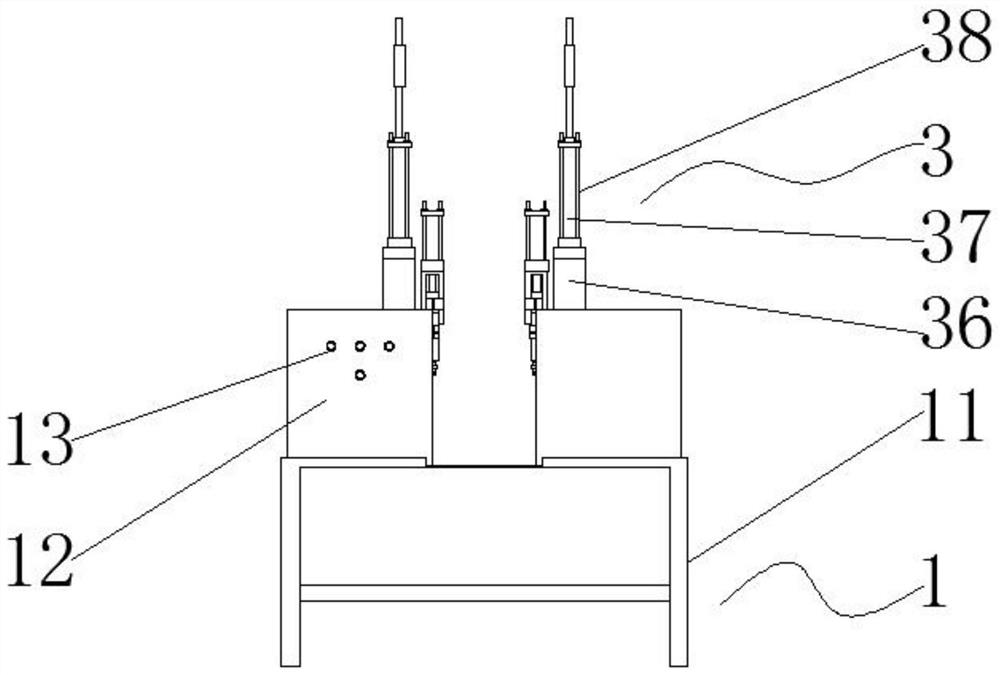
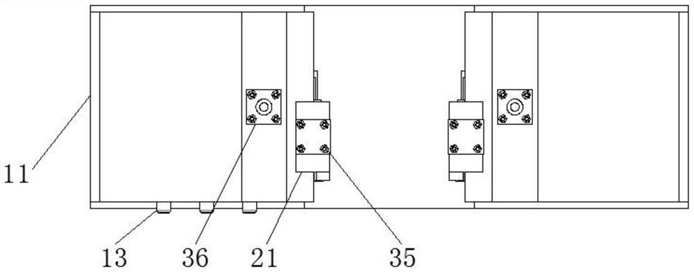
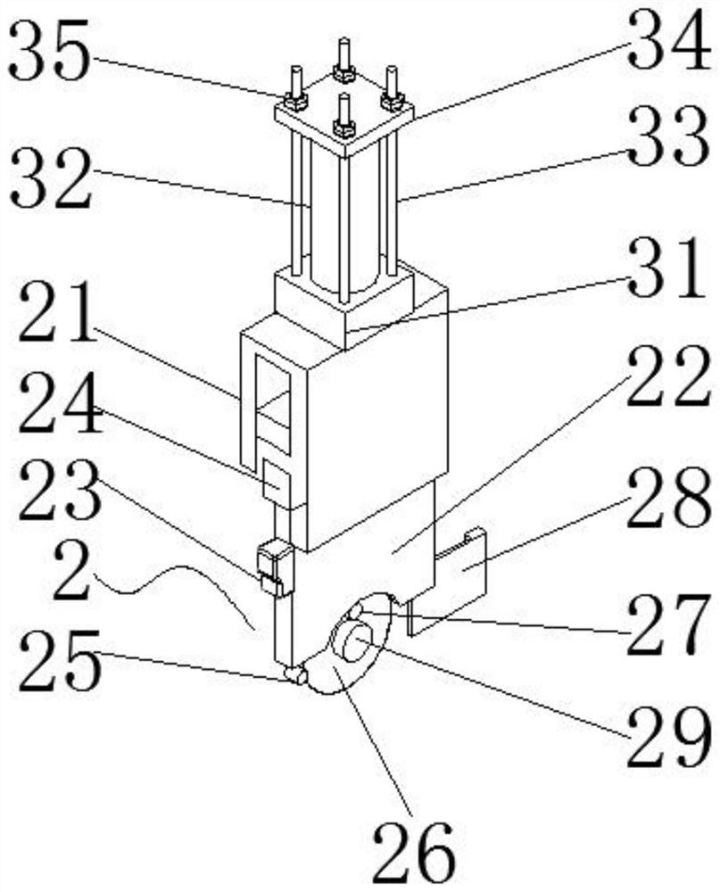
[0018] see Figure 1-3 , the present invention provides a technical solution: a bucket handle end forming machine, including a fixed assembly 1, a moving assembly 2, a hydraulic assembly 3 and a rotating assembly 4, the fixed assembly 1 includes a workbench 11, a hydraulic tank 12 and a control button 13 , The workbench 11 is fixedly connected with the hydraulic tank 12, the hydraulic tank 12 is located above the workbench 11, the control button 13 is fixedly connected with the hydraulic tank 12, the control button 13 is located at the front end of the hydraulic tank 12, and the hydraulic tank 12 i...


PUM


Abstract

The invention belongs to the technical field of handle forming, and provides a barrel handle end forming machine. The barrel handle end forming machine comprises a fixed assembly, a movable assembly,a hydraulic assembly and a rotating assembly. The fixed assembly comprises a worktable, hydraulic boxes and control buttons. The worktable and the hydraulic boxes are fixedly connected. The hydraulicboxes are located above the worktable. The control buttons are fixedly connected with the hydraulic boxes and located at the front ends of the hydraulic boxes. By arranging the two hydraulic boxes, hydraulic forming power of the machine is increased greatly, and the effect of machining different varieties and specifications of products is better; power of a first hydraulic tank downwards pushes amovable plate to generate friction with an outer disc at the bottom, thus the two tips of the barrel handle end can be fixed better, and hydraulic stability of the forming machine is improved; and bysetting the pressure generated by a second hydraulic tank, a sliding strip downwards drives a connecting shaft to rotate for machining, operating is convenient, and thus the production efficiency is improved.

Description

technical field [0001] The invention belongs to the technical field of handle forming, in particular to a barrel handle end forming machine. Background technique [0002] The forming machine, also known as the unpacking machine, refers to the automatic completion of unpacking, forming, and bending of the lower bottom hinge. At present, the lower part of the tape is pasted, the box board folded into cardboard is opened, the bottom of the box is folded according to a certain procedure, and the tape is sealed and then transported to the special equipment of the box packing machine. Automatic carton forming machine and automatic unpacking machine are assembly line equipment for automatic unpacking of large quantities of cartons, automatic folding of the lower cover, and automatic sealing of the bottom tape. device of. [0003] The original barrel handle end forming machine uses traditional mechanical transmission, which has a small forming force, resulting in fewer specificati...

Claims


Application Information

Patent Timeline
Patent Type & Authority Patents(China)
IPC IPC(8): B31B50/86
CPCB31B50/86
Inventor 石中平苏苗花
Owner 芜湖立新清洁用品有限公司
Why Eureka
Try Eureka