
Efficient conveying mechanism for large shaft workpieces

A technology for shaft workpieces and conveying mechanisms, which is applied in the field of high-efficiency conveying mechanisms for large shaft workpieces. It can solve problems such as stuck vibrating discs, poor effects, and difficult conveying processes, and achieves difficult feeding and fast and orderly arrangement. Effect

Pending Publication Date: 2019-01-04
JIANGSU XINTIMU INTELLIGENT EQUIP CO LTD
View PDF0 Cites 0 Cited by
  • Summary
  • Abstract
  • Description
  • Claims
  • Application Information

AI Technical Summary

Problems solved by technology

At present, the effective method is to use a vibrating plate to achieve the completion, but for the shaft workpiece with a long length, such as the drive shaft of a car, this form is not suitable, and its axially extending body often gets stuck. The vibrating plate, or the shaft workpieces will interfere with each other and will not form an orderly arrangement on the vibrating plate; further, when the feeding area includes a height difference and needs to be transported from a low place to a high place , the delivery process is more difficult and the effect is even worse

Method used


Image

  • Efficient conveying mechanism for large shaft workpieces
  • Efficient conveying mechanism for large shaft workpieces
  • Efficient conveying mechanism for large shaft workpieces

Examples


Embodiment Construction

[0023] In order to enable those skilled in the art to better understand the technical solutions of the present invention, the present invention will be further described in detail below in conjunction with specific embodiments.

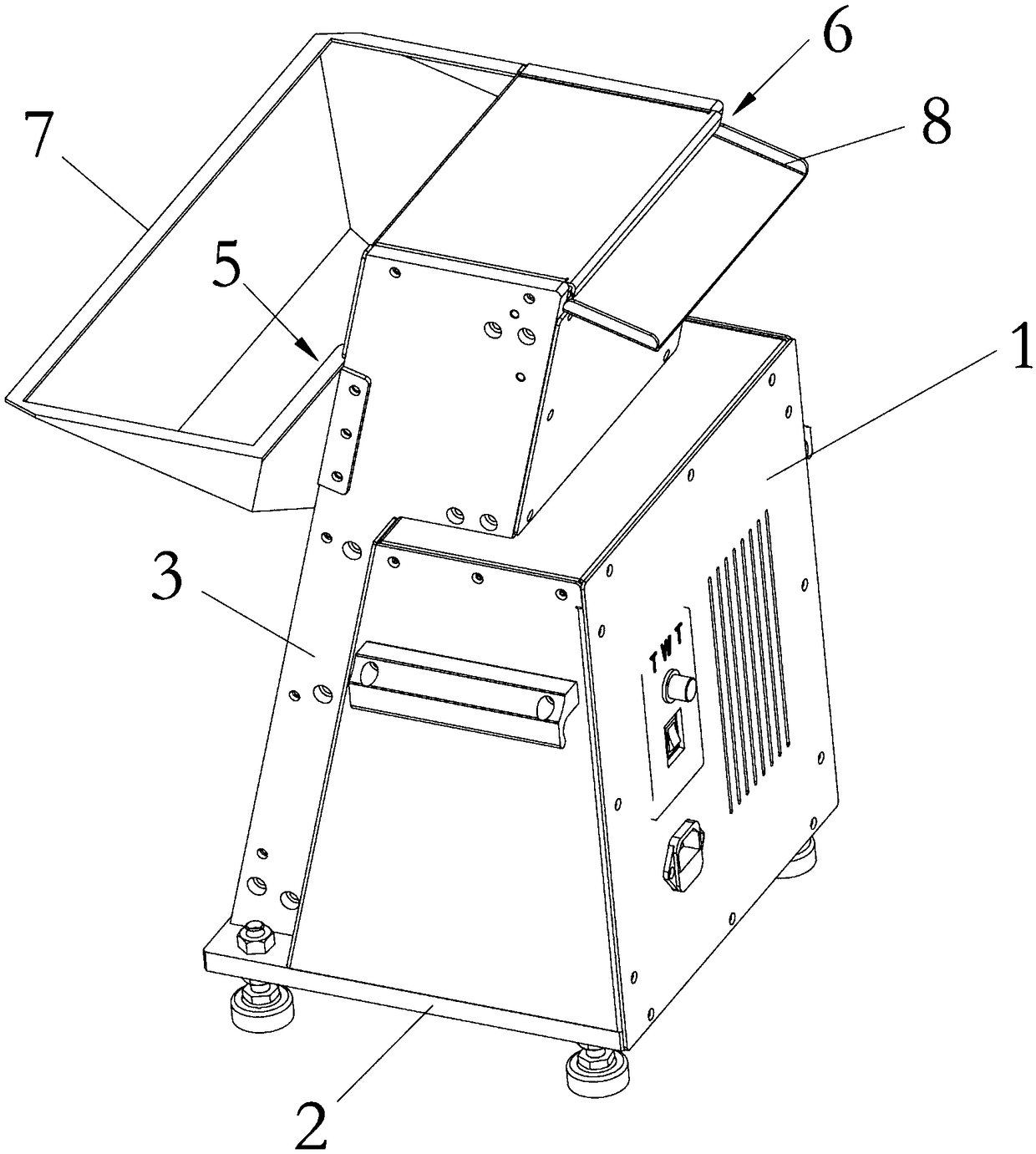
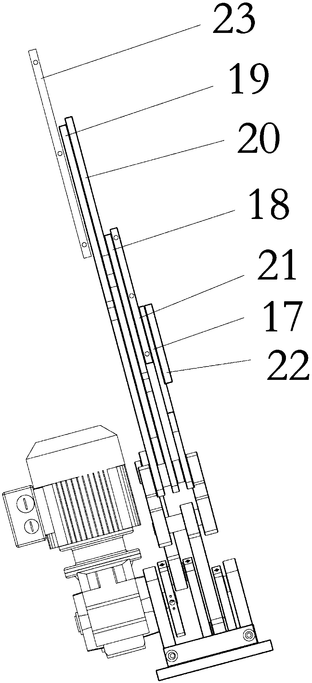
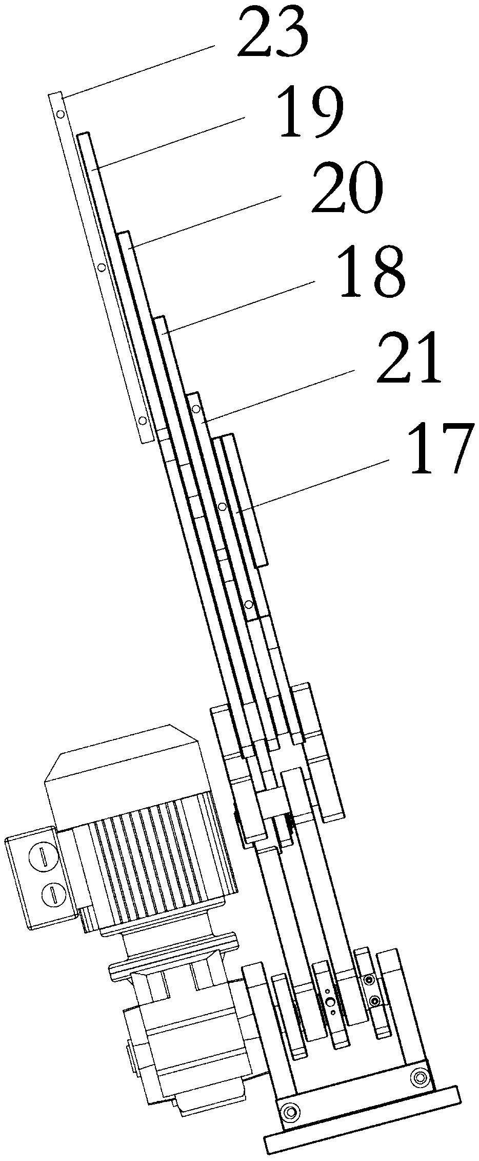
[0024] The invention discloses a high-efficiency conveying mechanism for large-scale shaft workpieces, such as figure 1 As shown, it includes: a frame, and an outer cover 1 arranged on the frame. The frame includes a horizontal base 2, which is directly and horizontally placed on the ground or other horizontal surfaces, where the placement can be mobile or fixed. Two vertical boards 3 are fixed on the base 2 , and a base 4 is fixed between the vertical boards 3 . In this preferred embodiment, the base 4 is fixed obliquely, that is, it is set at an angle to the horizontal plane. Those skilled in the art should know that the shape of the frame can be varied, for example, the shape of the outer cover can be arc-shaped, the shape of the base 2 can be ot...


PUM


Abstract

The invention discloses an efficient conveying mechanism for large shaft workpieces. The efficient conveying mechanism comprises a rack and a stepping lifting mechanism arranged in the rack. The stepping lifting mechanism comprises a reciprocating driving assembly and a reciprocating push plate set. The reciprocating driving assembly comprises a motor and a crank set driven by the motor. The crankset comprises a self-rotation rotating block, and two pivot fulcrums are arranged on the rotating block relative to the self-rotation axis. Connecting rods are connected to the fulcrums correspondingly. The other ends of the connecting rods are provided with two conveying push plates or a transferring push plate in a pivoted mode. When the transferring push plate is located on two limiting positions where the transferring push plate moves in a reciprocating mode, the upper end face of the transferring push plate is flushed with the upper end faces of the two conveying push plates. The problemthat the shaft workpieces are difficult to feed is solved effectively, the ingenious and reliable effects are achieved, the shaft workpieces can be distributed quickly and orderly, and the function that the shaft workpieces are conveyed from the low positions to the high positions is achieved.

Description

technical field [0001] The invention relates to the technical field of automation equipment, in particular to a high-efficiency conveying mechanism for large shaft workpieces. Background technique [0002] At present, automation equipment is generally used in production activities. The advantage of automation equipment is that it can liberate operators well and greatly improve work efficiency. The basic functions of automation equipment generally include feeding area, processing area and unloading area. The feeding area includes the feeding mechanism of the basic workpiece or raw material, whose purpose is to transport the basic workpiece or raw material to the processing area; the processing area is generally the core of the automation equipment, and its purpose is to complete the automatic processing and testing of the basic workpiece or raw material ; The unloading area includes the feeding mechanism of the processed workpieces, the purpose of which is to transport and p...

Claims


Application Information

Patent Timeline
IPC IPC(8): B65G25/08
CPCB65G25/08
Inventor 戴杰王炜孟玉波
Owner JIANGSU XINTIMU INTELLIGENT EQUIP CO LTD
Learn More