Energy-saving magnetic medium deflocculation and separation integrated machine

A magnetic medium and energy-saving technology, applied in the field of water treatment, can solve the problems of affecting the floc recovery effect of the magnetic separation unit, not being able to be adsorbed cleanly by the magnetic medium, and reducing the recovery rate of the magnetic medium. , reduce the effect of specification design and configuration

Pending Publication Date: 2019-01-04
贾伯林
View PDF9 Cites 0 Cited by
  • Summary
  • Abstract
  • Description
  • Claims
  • Application Information

AI Technical Summary

Problems solved by technology

[0004] ① After the magnetic medium flocs are broken in the deflocculation unit, on the way into the magnetic separation unit, the flocs will undergo another flocculation process due to passing through a section of pipeline, so that the flocs will be formed again, thus affecting the magnetic separation unit flocs. Recycling effect, resulting in lower recovery rate of magnetic media
[0005] ② The separate deflocculation unit and magnetic separation unit need enough space for installation, which has limitations in places with tight space. At the same time, in order to make the flocs enter the magnetic separation unit, it is necessary to heighten the deflocculation unit. It is necessary to lay out the equipment foundation, which increases the cost of civil engineering
[0006] ③ Since the deflocculation unit and the magnetic separation unit are set separately, the pipeline installation between the two will become cumbersome
Because the magnetic medium is relatively small, the power of the magnetic drum and drive motor of the magnetic separation unit is generally selected relatively large, and the power consumption is often relatively high when the equipment is running.
[0008] ⑤ The broken flocs enter the magnetic separation unit, because the particle size of the magnetic medium in the flocs is too small, the permanent magnet in the magnetic drum cannot completely absorb the magnetic medium, resulting in the loss of part of the magnetic medium and reducing the recovery of the magnetic medium Rate

Method used


Image

  • Energy-saving magnetic medium deflocculation and separation integrated machine
  • Energy-saving magnetic medium deflocculation and separation integrated machine

Examples


Embodiment Construction

[0027] In order to make the purpose, technical solution and advantages of the present invention clearer, the following will further describe the implementation of the present invention in detail in conjunction with the accompanying drawings.

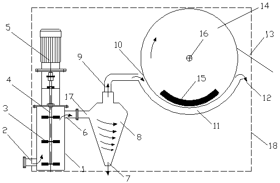
[0028] Such as figure 1 As shown, an energy-saving magnetic medium deflocculation and separation integrated machine, the main body is a deflocculation unit 1, a sand-water separator 8 and a magnetic separation unit 14, the deflocculation unit 2 is placed vertically or horizontally in the axial direction, and the motor of the deflocculation unit 5 drives the rotating shaft 4 of the deflocculating unit, the rotating shaft 4 of the deflocculating unit is fixedly connected with the blade 3, the feed port 2 of the deflocculating unit is set at the bottom of the cylinder, the discharge port 6 of the deflocculating unit is set at the top of the other side, and the sand-water separator enters The feed port 17 is flange-connected with the dischar...


PUM


Abstract

The invention provides an energy-saving magnetic medium deflocculation and separation integrated machine. A main body consists of a deflocculation unit, a magnetic separation unit and a sand-water separator. According to the energy-saving magnetic medium deflocculation and separation integrated machine provided by the invention, a sand-water separator is arranged between the deflocculation unit and the magnetic separation unit, so that flocs after deflocculation by the deflocculation unit can be immediately subjected to solid-liquid separation, the processing load of the magnetic separation unit in a subsequent section can be reduced, the energy consumption during operation of the magnetic separation unit can be reduced, the recovery rate of magnetic medium powder can be improved, and theoperation cost of water treatment can be reduced; and by adopting an integrated design, only a feed port and a discharge port need to be provided during field mounting, so that complicated mounting processes are saved, and the use is simpler and more convenient.

Description

technical field [0001] The invention relates to the field of water treatment, in particular to the sufficient deflocculation and high-efficiency recycling of magnetic media in the water treatment process, in particular to an energy-saving magnetic medium deflocculation and separation integrated machine. Background technique [0002] The magnetic medium coagulation sedimentation process (also known as the weighing medium coagulation sedimentation process) can promote the flocs containing pollutants to a certain extent to be more rapid by adding magnetic media (also weighing medium or dense medium powder) as flocculation nuclei. It can also form larger magnetic media and sludge composite flocs (referred to as magnetic media flocs) in the same period of time through adsorption and bridging. At the same time, due to the high density of the flocculated particles of the magnetic medium, the density of the formed magnetic medium composite floc is also higher than that of the conven...

Claims


Application Information

Patent Timeline
Patent Type & Authority Applications(China)
IPC IPC(8): C02F9/12
CPCC02F1/38C02F1/481C02F1/488C02F2303/26
Inventor 贾伯林杨志宏曹爱辉张振华张梅朱兆祥郭建飞单锦良
Owner 贾伯林
Why Eureka
Try Eureka