Normal-pressure superheated steam using carbonization and pyrolysis equipment
A superheated steam, carbonization technology, applied in indirect heating dry distillation, special form dry distillation, petroleum industry, etc., can solve the problem of not being able to recycle exhaust heat
- Summary
- Abstract
- Description
- Claims
- Application Information
AI Technical Summary
Problems solved by technology
Method used
Image

Examples
Embodiment 1
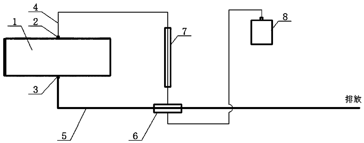
[0036] Such as figure 1 As shown, a carbonization and cracking device using normal pressure superheated steam includes a carbonization reactor 1. The carbonization reactor 1 is provided with a first air inlet 2 for injecting superheated steam and a first outlet for discharging steam. The air port 3, the first air inlet 2 is connected with an air inlet pipe 4, the first air outlet 3 is connected with an air outlet pipe 5, and the first air inlet 2 and the first air outlet 3 are provided Superheated steam generating mechanism.
[0037] The superheated steam generating mechanism includes a first heat exchanger 6 whose air outlet is in communication with the air inlet pipe 4, a reheat electromagnetic coil 7 arranged on the air inlet pipe 4, and its air outlet is connected to the air inlet pipe 4. A steam generator 8 communicates with the air inlet of the first heat exchanger 6, and the first heat exchanger 6 is arranged on the air outlet pipe 5.
[0038] In this embodiment, a carboniz...
Embodiment 2
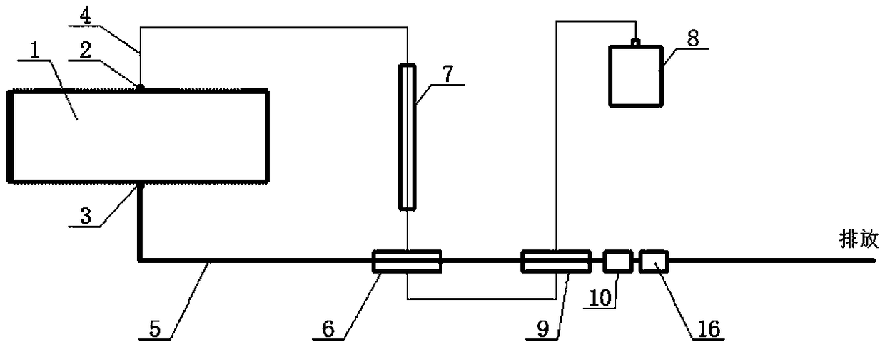
[0040] Such as figure 2 As shown, the difference from Embodiment 1 is that a temperature sensor for detecting the temperature of the steam discharged from the first heat exchanger 6 is provided in the direction of the air outlet of the first heat exchanger 6.
[0041] A second heat exchanger 9 is connected between the air inlet of the first heat exchanger 6 and the air outlet of the steam generator 8 through a pipe, and the second heat exchanger 9 is located downstream of the first heat exchanger 6 On the outlet pipe 5.
[0042] A catalytic cracking device 10 and a combustor 16 are sequentially arranged on the gas outlet pipe 5 downstream of the second heat exchanger 9 from upstream to downstream.
[0043] In this embodiment, in order to facilitate monitoring of the temperature of the steam discharged from the first heat exchanger, a temperature sensor is arranged in the direction of the outlet of the first heat exchanger; in addition, in order to make full use of the gas discharged...
Embodiment 3
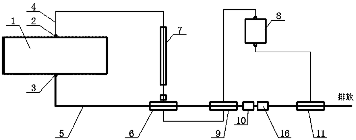
[0045] Such as image 3 As shown, the difference from Embodiment 2 is that a third heat exchanger 11 is provided on the gas outlet pipe 5 downstream of the combustor 16, and the gas outlet of the third heat exchanger 11 and the steam generator The air inlet of 8 is connected.
[0046] In this embodiment, in order to make full use of the heat in the high-temperature gas produced by the combustor, a third heat exchanger is provided on the gas outlet pipe downstream of the combustor, and the gas outlet of the third heat exchanger is connected to the inlet of the steam generator. 口Connected.
PUM
 Abstract
Description
Claims
Application Information
 - R&D
- Intellectual Property
- Life Sciences
- Materials
- Tech Scout
- Unparalleled Data Quality
- Higher Quality Content
- 60% Fewer Hallucinations
Browse by: Latest US Patents, China's latest patents, Technical Efficacy Thesaurus, Application Domain, Technology Topic, Popular Technical Reports.
© 2025 PatSnap. All rights reserved.Legal|Privacy policy|Modern Slavery Act Transparency Statement|Sitemap|About US| Contact US: help@patsnap.com