High-pressure-resistant large-flow miniaturized gas booster pump

A large-flow, high-pressure-resistant technology, applied in the field of mechanical transmission, can solve the problems of large power consumption, large volume and weight, and bulky parts of circulating pumps, and achieve the effects of low power consumption, light weight, and less materials

Pending Publication Date: 2021-03-26
深圳太科飞天科技有限公司
View PDF0 Cites 0 Cited by
  • Summary
  • Abstract
  • Description
  • Claims
  • Application Information

AI Technical Summary

Problems solved by technology

[0004] The current gas booster pumps mainly have the following disadvantages: 1. Poor high pressure resistance. Gas circulation pumps are often used in various high-pressure occasions. The high-pressure gas inside and the normal pressure outside form a huge pressure difference. The pressure difference puts forward strict requirements on the high pressure resistance and sealing performance of the components inside the circulating pump. However, due to the influence of materials, assembly processes and sealing methods, the current pressure resistance of the circulating pump needs to be improved.
2. The driving flow rate is small. When the gas pressure in the circulating pump is high, the leakage of the device itself will be large. In addition, the internal flow rate that can be driven is generally small due to the influence of air tightness and input power.
3. The volume is bulky and heavy. In order to be able to output high-pressure gas, various parts of the gas circulation pump, such as pipes, swivels, compressed air pistons and pipe joints, need to be designed to withstand high pressure, resulting in more materials used for each part and volume. and heavier
4. The power consumption is relatively large. Due to the large pressure difference between the inside and outside of the circulating pump and the heavy weight of each component, the input power required to drive the motor and compressor required for the work of each component is relatively large, resulting in the overall consumption of the circulating pump. higher power

Method used


Image

  • High-pressure-resistant large-flow miniaturized gas booster pump
  • High-pressure-resistant large-flow miniaturized gas booster pump
  • High-pressure-resistant large-flow miniaturized gas booster pump

Examples


Embodiment Construction

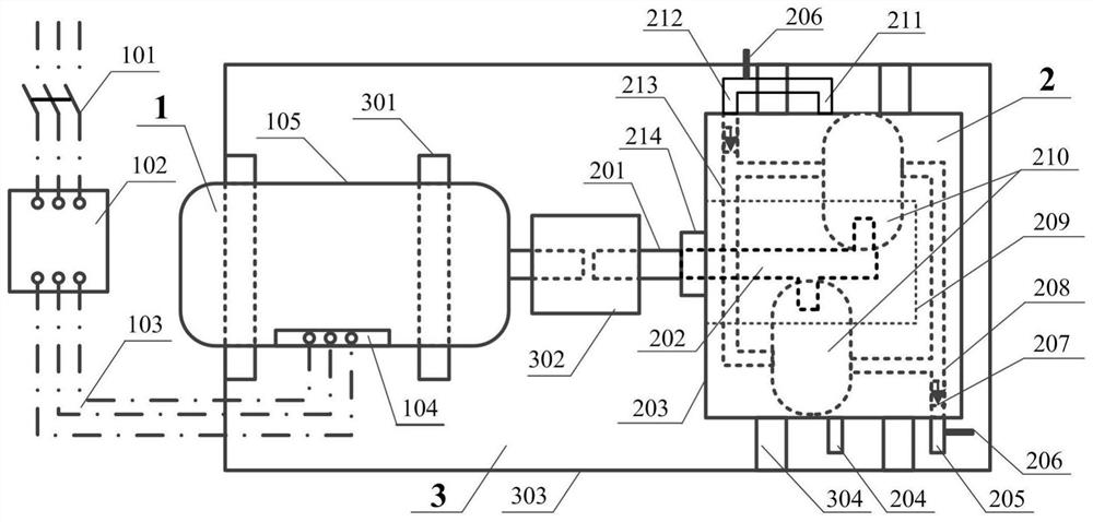
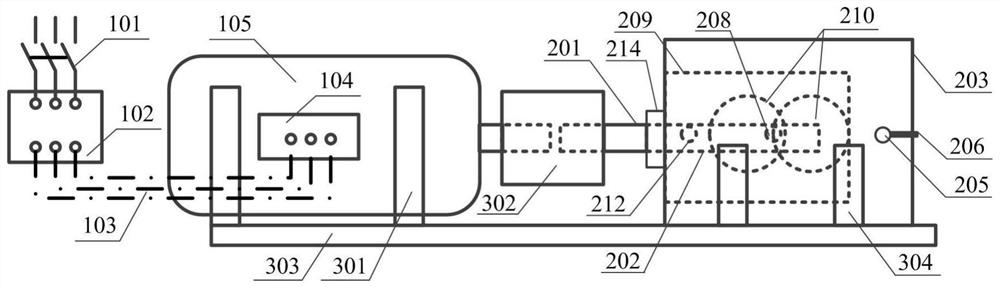
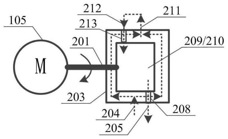
[0027] Such as figure 1 , figure 2 , image 3 , Figure 4 , Figure 5 , Figure 6 As shown, the miniaturized gas booster pump with high pressure resistance and large flow rate of the present invention includes an electrical system 1 and a circulation pump cavity 2, the electrical system 1 and the circulation pump cavity 2 are connected together through a connecting part 3, and the circulation pump The cavity 2 includes a housing 203, the housing is provided with a plunger pump 210, the housing 203 is provided with a cavity gas inlet 204 and a cavity gas outlet 211, the plunger pump gas outlet 205 protrudes from the housing, and the cavity gas The outlet 211 is connected to the gas inlet 212 of the plunger pump, so that the input gas pressure of the plunger pump is equal to the internal pressure of the casing.

[0028] In the miniaturized gas booster pump with high pressure resistance and high flow rate of the present invention, the gas outlet 205 of the plunger pump and ...


PUM


Abstract

The invention discloses a high-pressure-resistant large-flow miniaturized gas booster pump which comprises an electrical system and a circulating pump cavity, wherein the electrical system is connected with the circulating pump cavity through a connecting part, the circulating pump cavity comprises a shell, a plunger pump is arranged in the shell, a cavity gas inlet and a cavity gas outlet are formed in the shell, a plunger pump gas outlet extends out of the shell, and the cavity gas outlet is connected with a plunger pump gas inlet, so that the input gas pressure of the plunger pump is equalto the internal gas pressure of the shell. The high-pressure-resistant large-flow miniaturized gas booster pump has the characteristics of being small in size, light in weight and low in power consumption. The high-pressure-resistant large-flow miniaturized gas booster pump has wide application prospects in the fields of chemical engineering, aerospace, fire protection and the like.

Description

technical field [0001] The invention belongs to the field of mechanical transmission, and mainly relates to a miniaturized gas booster pump with high pressure resistance and large flow rate. [0002] technical background [0003] As a relay device for increasing gas pressure and maintaining gas circulation, gas booster pump has broad application prospects in chemical industry, aerospace, fire protection and other fields. The working principle of the gas circulation pump is as follows: driven by the motor, the mechanical eccentric device inside the circulation pump drives the cavity inside the pump to reciprocate, thereby compressing and stretching the gas in the pump cavity with a fixed volume to form a vacuum ( Negative pressure), there is a pressure difference between the pump suction port and the inlet gas. Under the action of the pressure difference, the gas is sucked into the pump cavity. After compression, the low-pressure inlet gas becomes high-pressure gas and is disc...

Claims


Application Information

Patent Timeline
Patent Type & Authority Applications(China)
IPC IPC(8): F04B35/04F04B27/02F04B49/20F04B39/10F04B39/12F04B39/06
CPCF04B27/005F04B27/02F04B35/04F04B39/06F04B39/10F04B39/121F04B49/20
Inventor 尹永利熊凯贺青云高彦鹏樊强黄河静
Owner 深圳太科飞天科技有限公司
Why Eureka
Try Eureka