Drainage construction method for tunnel passing through clastic rock steeply inclined reverse thrust water-rich fault

A technology for tunnel drainage and construction methods, applied in drainage, tunnels, earth-moving drilling and mining, etc., can solve problems such as catastrophic consequences, affecting construction safety and efficiency, and slow construction progress.

Active Publication Date: 2019-01-04
THE NO 6 ENG CO LTD OF CHINA RAILWAY 20TH BUREAU GRP
View PDF6 Cites 9 Cited by
  • Summary
  • Abstract
  • Description
  • Claims
  • Application Information

AI Technical Summary

Problems solved by technology

Tunnel construction in clastic rock strata is difficult, especially when the stratum is a water-rich stratum rich in groundwater. Rock mass fragmentation provides more favorable conditions for the occurrence and enrichment of groundwater, and the construction is very difficult. Large, water gushing and sand gushing are very likely to occur during construction. In addition, the inclination angle of the fault section is greater than 60°, which can easily cause catastrophic consequences and seriously affect the safety and efficiency of construction.
Therefore, when constructing tunnels that cross steeply inclined th

Method used


Image

  • Drainage construction method for tunnel passing through clastic rock steeply inclined reverse thrust water-rich fault
  • Drainage construction method for tunnel passing through clastic rock steeply inclined reverse thrust water-rich fault
  • Drainage construction method for tunnel passing through clastic rock steeply inclined reverse thrust water-rich fault

Examples


Embodiment Construction

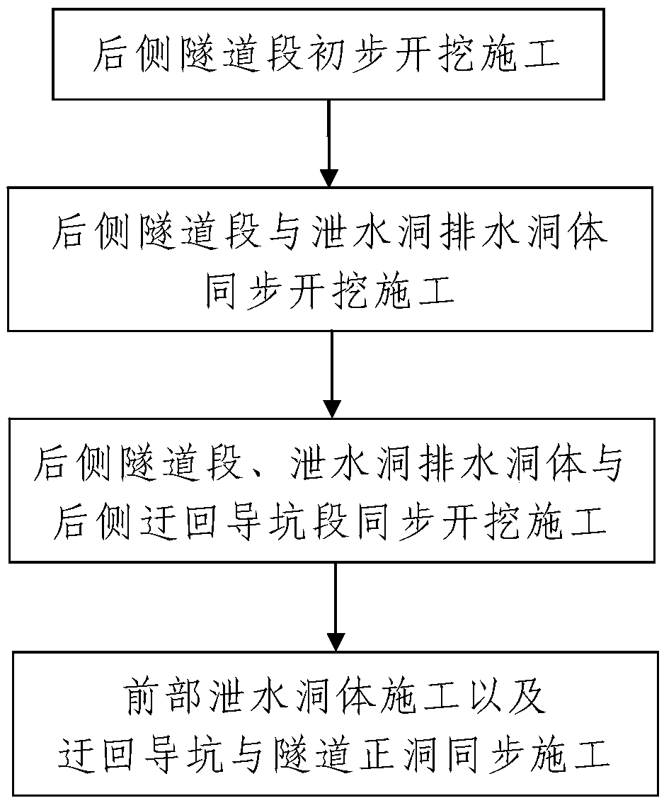
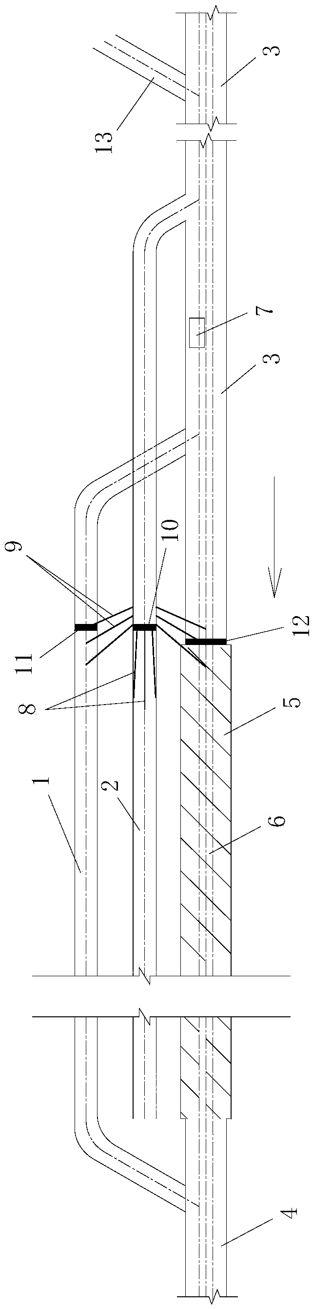
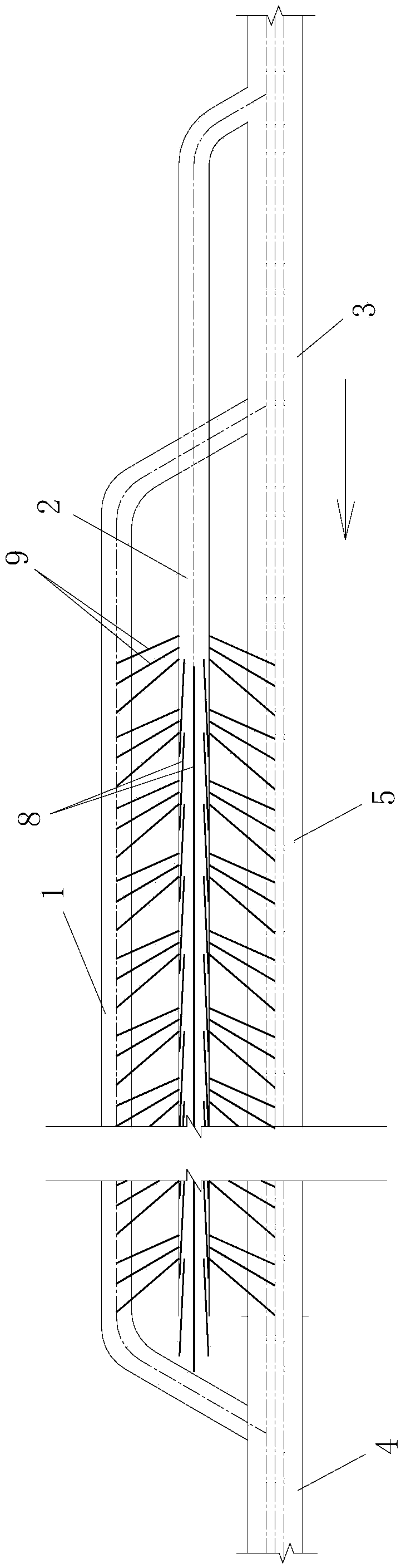
[0095] Such as figure 1 Shown is a drainage construction method for tunnels passing through steep clastic rock thrusting water-rich faults. The main tunnel of the constructed tunnel is divided into a rear tunnel section 3, a front tunnel section 4 located in front of the rear tunnel section 3, and a connecting tunnel section. The middle tunnel section 5 between the rear tunnel section 3 and the front tunnel section 4 and passing through the clastic rock steep thrust water-rich fault 6, see figure 2 , image 3 and Figure 4 On the same side of the tunnel being constructed, there is a roundabout pilot pit 1 and a drainage tunnel 2, both of which pass through the clastic rock steeply dipping water-rich fault 6 from the back to the front. The tunnel hole; the detour guide pit 1 is a detour guide pit excavated between the rear tunnel section 3 and the front tunnel section 4, and the detour guide pit 1 and the main tunnel of the constructed tunnel are laid in the same On the hor...


PUM

PropertyMeasurementUnit
Lengthaaaaaaaaaa

Abstract

The invention discloses a drainage construction method for a tunnel passing through a clastic rock steeply inclined reverse thrust water-rich fault. The drainage construction method is characterized in that a construction tunnel main cave is divided into a rear side tunnel section, a front side tunnel section and a middle portion tunnel section passing through the clastic rock steeply inclined reverse thrust water-rich fault, wherein a by-pass pilot tunnel and a drain cavern are formed in the same side of the construction tunnel main cave. When drainage construction is carried out in the construction tunnel main cave, the drainage construction method comprises the steps of: 1, carrying out preliminary excavation construction on the rear side tunnel section; 2, synchronously carrying out excavation construction on the rear side tunnel section and a drainage hole body of the drain cavern; 3, synchronously carrying out excavation construction on the rear side tunnel section, the drainagehole body of the drain cavern and a rear side by-pass pilot tunnel section; 4, and carrying out construction on the front portion drainage hole body, and synchronously carrying out construction on theby-pass pilot tunnel and the tunnel main cave. The drainage construction method provides a new construction working plane by means of the by-pass pilot tunnel, improves the working efficiency, provides the high-altitude drainage hole between the tunnel main cave and the by-pass pilot tunnel, can drain water embedded in the fault to the greatest extent, reduces water pressure in the fault in frontof a tunnel face, ensures safety construction of each tunnel face and can shorten the construction period.

Description

technical field [0001] The invention belongs to the technical field of tunnel construction, and in particular relates to a drainage construction method for tunnels passing through clastic rocks steeply dipping and thrusting water-rich faults. Background technique [0002] The fault zone refers to the zone composed of the main fault plane and the broken rock blocks on both sides, as well as several secondary faults or rupture surfaces. In China, a high-angle thrust fault with a dip angle greater than 45° or 30° is called a thrust fault, and it is more difficult to construct a tunnel that crosses a steep thrust fault with a dip angle greater than 60°. Thrust faults greater than 60°. Clastic rock refers to the rock formed by the transport, deposition, compaction and cementation of minerals and rock debris produced by mechanical weathering of the parent rock; its components include matrix and cement in addition to clastic particles. Tunnel construction in clastic rock strata i...

Claims


Application Information

Patent Timeline
IPC IPC(8): E21F16/02E21D9/14
CPCE21D9/14E21F16/02
Inventor 王存宝赵志辉段锋李瑛胡晓辉李奕郑大伟
Owner THE NO 6 ENG CO LTD OF CHINA RAILWAY 20TH BUREAU GRP
Why Eureka
Try Eureka