Water turbine

A technology for water turbines and runners, applied in hydropower, mechanical equipment, engine components, etc., can solve the problems of high cost of seals, difficult to ensure assembly accuracy, high maintenance costs, etc., to reduce axial force, simple and reliable structure , the effect of reducing the difficulty of assembly

Active Publication Date: 2019-01-04
江西省莲花水轮机厂有限公司
View PDF6 Cites 0 Cited by
  • Summary
  • Abstract
  • Description
  • Claims
  • Application Information

AI Technical Summary

Problems solved by technology

[0004] Second, the impurity particles in the water flow will be brought into the gap between the runner and the volute, and long-term accumulation will cause the contact surface between the runner and the volute to wear and affect the service life of the runner
[0005] Third, the continuous high-pressure water flow will always maintain a large axial thrust between the runner and the volute, so the bearing of the runner will continue to bear a large axial force, which will inevitably lead to the acceleration of the bearing wear and tear
[0006] Of course, in the prior art, it has also been considered to install a sealing structure between the runner and the volute, but since the operatin

Method used


Image

  • Water turbine
  • Water turbine
  • Water turbine

Examples


Embodiment 1

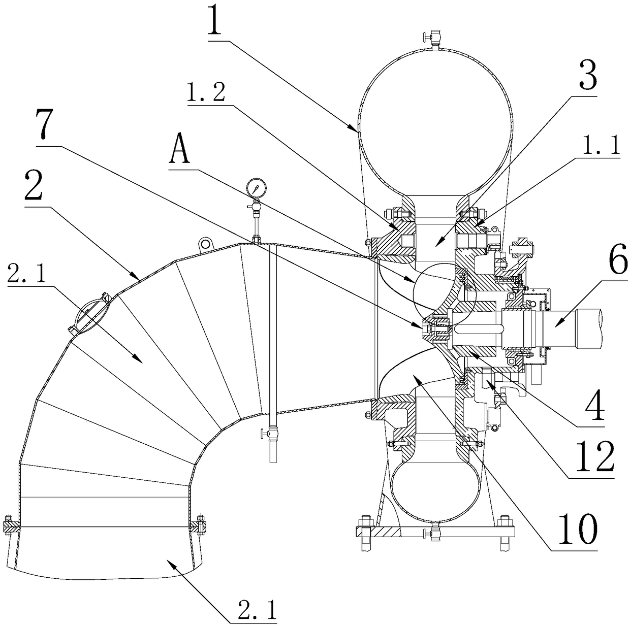
[0029] The invention provides a water turbine, which includes such as figure 1 As shown in the volute 1 and the draft tube 2, the outer wall of the volute 1 is provided with a water inlet, and the center of the volute 1 is provided with a water outlet 3, and the draft tube 2 and the water outlet 3 of the volute 1 Connected so that the pipeline in the volute 1 communicates with the draft tube 2 to form a water flow channel, the pipeline in the volute 1 is in a spiral shape, and the volute 1 is provided with a runner 4, and the runner 4 and The volute 1 rotates and fits, and the volute 1 is provided with a mounting groove for installing the runner 4. When the runner 4 rotates and fits in the mounting groove, the part of the runner 4 is located in the water flow channel and passes through the water flow channel. The flow of the water flow drives the runner 4 to rotate, so that the water flow in the volute 1 can be converted into the mechanical energy of the runner 4 . The runner...

Embodiment 2

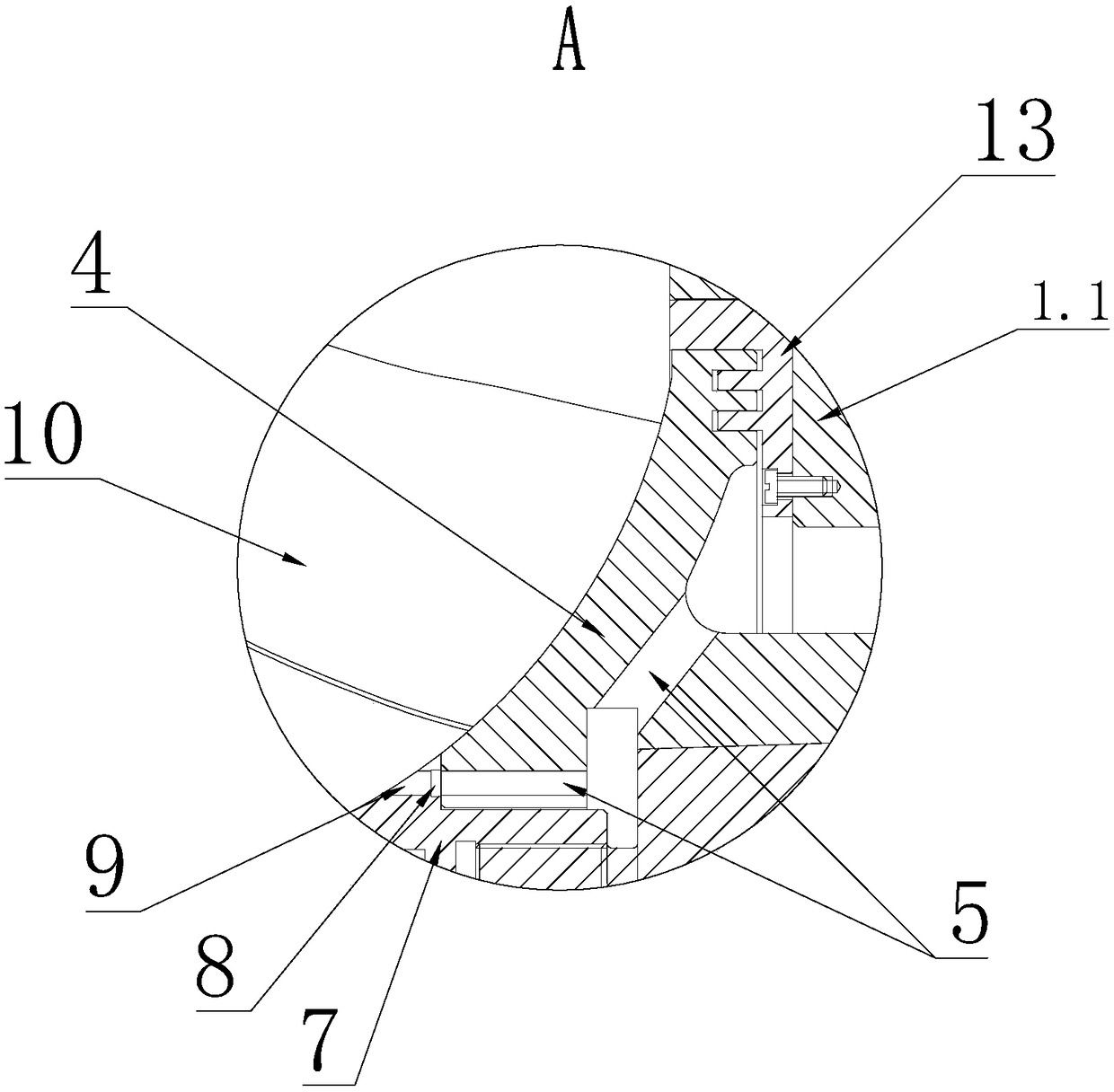
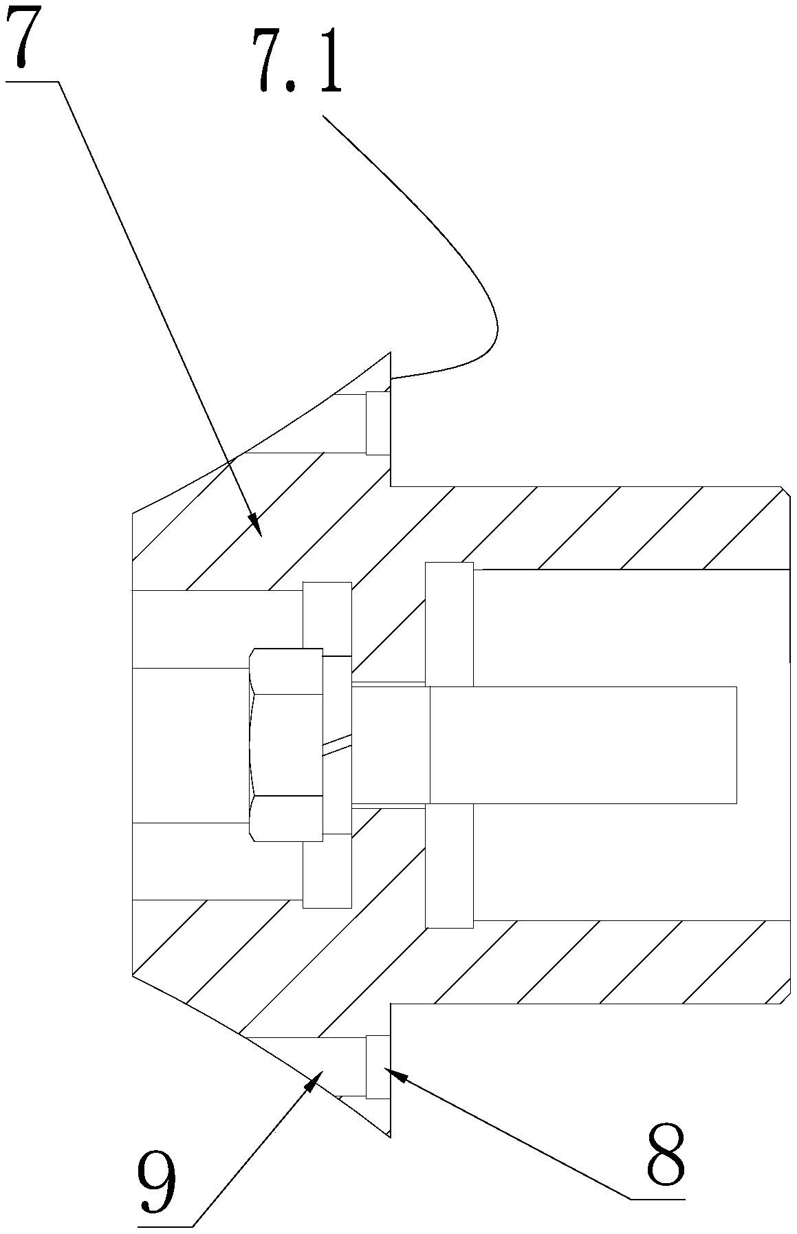
[0031] Its basic mechanism is the same as that of Embodiment 1, the difference is that: the rear end surface 7.1 of the water discharge cone 7 facing the runner 4 is provided with a plurality of arc-shaped grooves 8, and all arc-shaped grooves 8 are arranged along the circumferential direction. They are arranged at intervals in sequence, and any two adjacent arc-shaped grooves 8 are connected through a connecting groove 11 , and the cross-sectional area of ​​the connecting groove 11 is smaller than that of the arc-shaped groove 8 . Preferably, the cross-sectional area of ​​the connecting groove 11 is equal to the cross-sectional area of ​​1 / 4 arc-shaped groove 8 . The core purpose of this design is to make a single pressure relief pipeline on the runner 4 correspond to a respective groove 8, thereby corresponding to a respective connecting pipe 9, and a plurality of connecting pipes 9 are not designed in parallel in the runner 4, through The dislocation distribution of the con...

Embodiment 3

[0033] Its basic mechanism is the same as that of Embodiment 2, the difference is that: the draft pipe 2 includes a tail water main pipe 2.1 and a tail water elbow 2.2, and the tail water main pipe 2.1 passes through the tail water elbow 2.2 and the water outlet of the volute 1 3 connected.


PUM


Abstract

The invention discloses a water turbine. The water turbine comprises a volute with an inner cavity and a tail water pipe. The tail water pipe communicates with a water outlet on the volute so that a water flow channel can be formed between the volute and the tail water pipe. A rotating wheel is arranged in the volute. The rotating wheel and the volute are in running fit, and a part of the rotatingwheel is located in the water flow channel. The water turbine is characterized in that a water drain pipeline is arranged in the rotating wheel, and a gap between the rotating wheel and the volute communicates with the water flow channel through a water drain pipeline, so that accumulated water in the gap between the rotating wheel and the volute flows back into the water flow channel through thewater drain pipeline. According to the water turbine, the pressure in the gap between the rotating wheel and the volute is reduced in a drainage manner, and therefore rotating resistance of the rotating wheel is reduced, the service life of the rotating wheel is prolonged, and the maintenance frequency is reduced.

Description

technical field [0001] The invention relates to the technical field of turbomachinery, in particular to a water turbine. Background technique [0002] The water turbine is an important energy conversion device that converts water flow energy into mechanical energy, and it is also an important core unit for hydropower generation in the utilization of new energy. The existing water turbine mainly includes a volute, a draft tube, a runner and a generator. The flowing water flows from the water inlet of the volute into the spiral and accelerates to form a high-pressure water flow that impacts the runner and is finally discharged through the draft tube. The wheel rotates, and then drives the generator to rotate and generate electricity through the transmission shaft. Since the part of the runner protrudes into the volute, there must be a rotation gap during the rotation of the runner and the volute, which will inevitably cause the water flow to enter the gap between the runner a...

Claims


Application Information

Patent Timeline
IPC IPC(8): F03B3/12F03B3/18F03B11/06
CPCF03B3/12F03B3/186F03B11/063Y02E10/20
Inventor 江泓洲
Owner 江西省莲花水轮机厂有限公司
Why Eureka
Try Eureka