Final transmission structure, bulldozer and turning control method

A technology of transmission structure and bulldozer, which is applied in the fields of final drive structure, bulldozer and turning control. It can solve the problems of large wheel-side deceleration structure, small transmission ratio, and difficulty in providing torque, etc., and achieve good application, stable transmission torque, and versatility high effect

Inactive Publication Date: 2019-01-04
SHANTUI CONSTR MASCH CO LTD
View PDF7 Cites 2 Cited by
  • Summary
  • Abstract
  • Description
  • Claims
  • Application Information

AI Technical Summary

Problems solved by technology

However, the main technical problems in the existing technology include: multi-stage planetary gears need to be equipped with multiple planetary ring gears correspondingly, so that the structure of the entire wheel-side reduction structure is relatively large and the compactness is poor; at the same time, on some heavy-duty reducers, the It is necessary to output greater torque at a lower vehicle speed. The existing three-stage reduction unit is difficult to provide greater torque because of the small transmission ratio.
[0004] At the same time, the bulldozers with the existing final drive structure have poor steering performance and can only provide one steering mode, that is, the bulldozer only has a large turning radius to turn a large bend.
When the bulldozer requires a sharp turn with a small turning radius under special working conditions, the bulldozer with the existing final drive structure cannot realize it at all, which reduces the functionality and versatility of the bulldozer

Method used


Image

  • Final transmission structure, bulldozer and turning control method
  • Final transmission structure, bulldozer and turning control method
  • Final transmission structure, bulldozer and turning control method

Examples


Embodiment 1

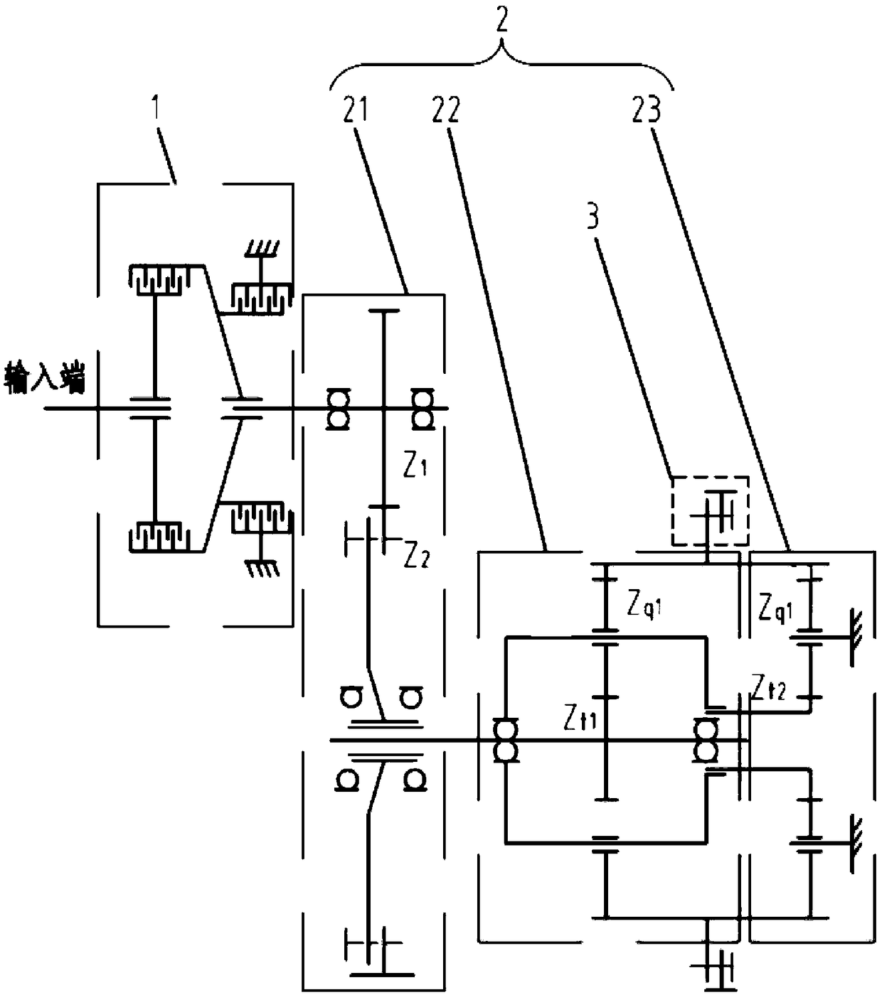
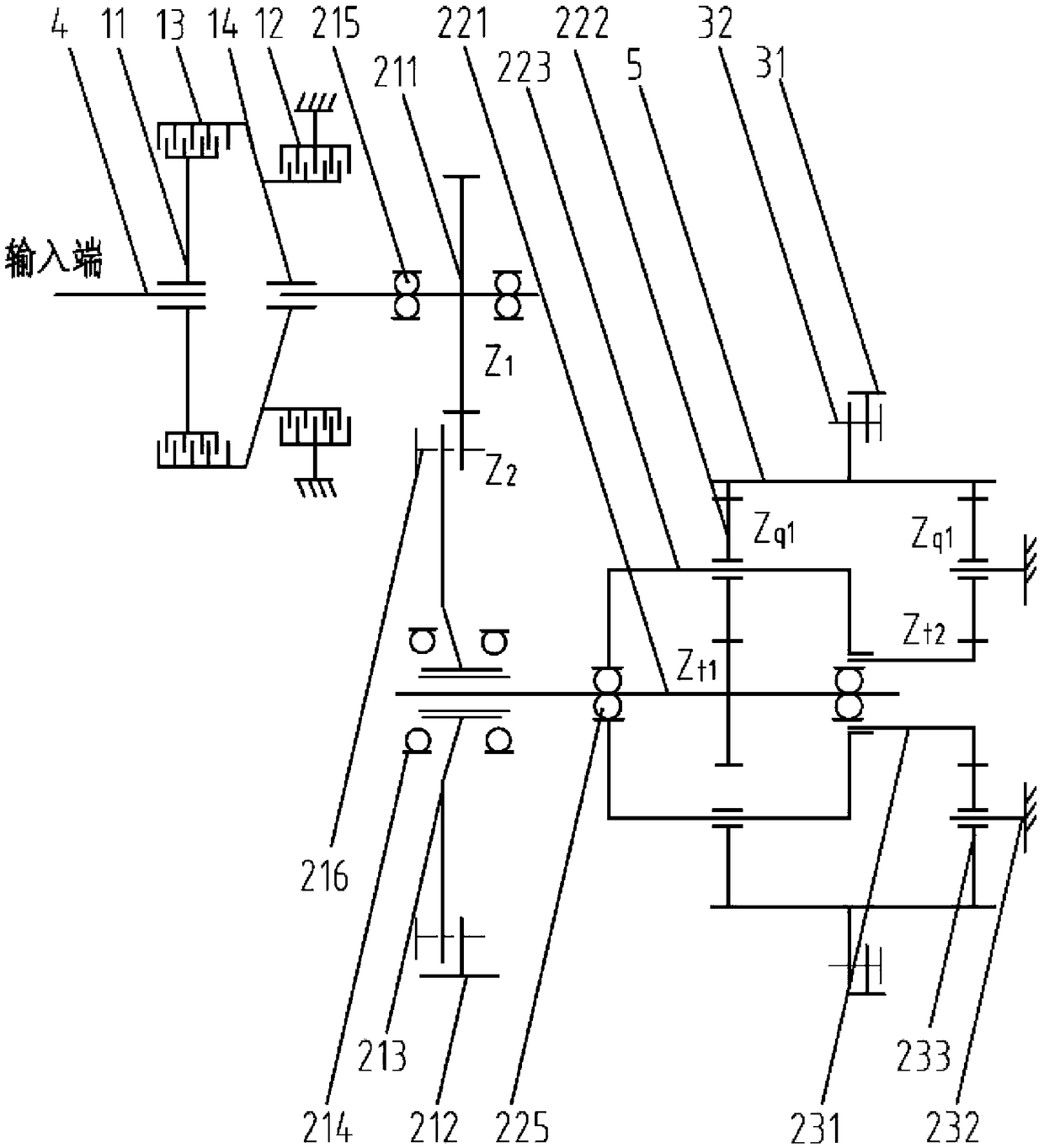
[0056] Embodiment 1 of the present invention provides a final drive structure, figure 1 It is a structural schematic diagram of multiple functional units in the final drive structure provided by Embodiment 1 of the present invention, from figure 1 It can be seen from the figure that it mainly includes the input shaft 4, the steering brake unit 1, the transmission unit 2 and the drive unit 3 connected in sequence, wherein the input shaft 4 is the power source, powered by the engine; the steering brake unit 1 is used to control the input power Transmission; the transmission unit 2 is used to achieve a larger transmission ratio; the drive unit 3 is used to connect with an external actuator to transmit power to the actuator, such as the wheel / walking track of an engineering vehicle. Among them, the steering brake unit 1 can be selectively unlocked or locked, so that the power of the input shaft 4 can be selectively transmitted to the transmission unit 2. The transmission unit 2 is...

Embodiment 2

[0078] The invention also provides a bulldozer, Image 6 It is a schematic diagram of the transmission structure of the bulldozer provided in Embodiment 2 of the present invention, Figure 7 It is a schematic diagram of the opening and closing process of the bulldozer's walking control. Image 6 and Figure 7 As shown, the bulldozer mainly includes an engine 61 providing power output, a hydraulic torque converter 62, a gearbox 63, a central transmission structure 64, a left final drive 71 and a right final drive 72, wherein the left final drive 71 and the right final drive 72 are the final drive structures in the first embodiment. like Image 6 As shown in , taking a bulldozer including two final drive structures as an example, the two final drive structures are respectively a left final drive 71 and a right final drive 72, and the left final drive 71 and the right final drive 72 are symmetrically arranged relative to the center of the car body, and the left The respective...

Embodiment 3

[0081] The invention also proposes a bulldozer turning control method, Figure 7 It is a schematic diagram of the walking operation, opening and closing process of the bulldozer provided in Embodiment 3 of the present invention, as shown in Figure 7 As shown in , the bulldozer walking states include forward, backward, left-turning, right-turning and other states, wherein turning left or turning right includes the first turning radius and the second turning radius, and the first turning radius is greater than the second turning radius Radius, that is, the first radius of rotation represents the bulldozer turning a large turn, and the second radius of rotation represents the bulldozer turning a sharp turn.

[0082] Specifically include:

[0083] (1) When the travel handle is in neutral (locking the car) or the engine is turned off, the left and right brakes and left and right clutches are locked;

[0084] (2) When the travel handle is in neutral (the lock lever is open), the ...


PUM


Abstract

The invention discloses a final transmission structure, a bulldozer and a turning control method, and relates to the technical field of bulldozers. In the final transmission structure, a steering brake unit comprises a brake, a driving hub, a clutch and a driven hub, wherein the brake is connected with an input shaft through the driving hub, the clutch is connected with a transmission unit througha driven hub, and the brake and the clutch can be selectively unlocked or locked. A first planetary gear ring and a second planetary gear ring form a planetary gear ring of an integrated structure. The bulldozer comprises an engine, a hydraulic torque converter and a gearbox which are connected in sequence. A central transmission structure is connected with the gearbox. A left final transmissionstructure and a right final transmission structure are both connected with the central transmission structure and are both of the final transmission structure. The bulldozer is adopted in the turningcontrol method. The final transmission structure can bear larger torque when rotated leftwards or rightwards, and torque transfer is stable. The turning control method has the large or small radius turning ability, and is high in universality.

Description

technical field [0001] The invention relates to the technical field of a bulldozer and a turning control method, in particular to a final drive structure, a bulldozer and a turning control method. Background technique [0002] The bulldozer final drive structure usually includes two forms: one is a two-stage spur gear final drive, and the other is a planetary gear final drive. The former is a traditional two-stage straight-tooth reduction structure, which is simple in structure, large in size, unbalanced in components, and cannot be modularized, making maintenance inconvenient. The latter gear modulus can be designed to be smaller, the structural size and space are small, the components are evenly stressed, and the torque transmission is relatively stable. There are two structural forms, modular and non-modular, and the assembly and maintenance of the modular structure is relatively convenient. [0003] The planetary gear reduction structure in the prior art adopts three-st...

Claims


Application Information

Patent Timeline
Patent Type & Authority Applications(China)
IPC IPC(8): F16H48/06F16H1/04F16H1/32F16H1/36F16D25/08F16D55/40B62D11/00B62D11/08E02F9/20
CPCB62D11/006B62D11/08E02F9/202F16D25/082F16D55/40F16D2121/04F16H1/04F16H1/32F16H1/36F16H48/06F16H2048/02
Inventor 续鲁宁蔡娟侯文军李宣秋宣苓娟
Owner SHANTUI CONSTR MASCH CO LTD
Why Eureka
Try Eureka